
Page 200 - T. Anderson-Fracture Mechanics - Fundamentals and Applns.-CRC (2005)
P. 200
1656_C004.fm Page 180 Thursday, April 21, 2005 5:38 PM
180 Fracture Mechanics: Fundamentals and Applications
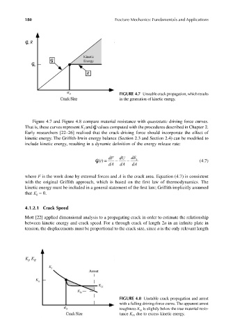
FIGURE 4.7 Unstable crack propagation, which results
in the generation of kinetic energy.
Figure 4.7 and Figure 4.8 compare material resistance with quasistatic driving force curves.
That is, these curves represent K and G values computed with the procedures described in Chapter 2.
I
Early researchers [22–26] realized that the crack-driving force should incorporate the effect of
kinetic energy. The Griffith-Irwin energy balance (Section 2.3 and Section 2.4) can be modified to
include kinetic energy, resulting in a dynamic definition of the energy release rate:
dF dU dE
G() = t − − k (4.7)
dA dA dA
where F is the work done by external forces and A is the crack area. Equation (4.7) is consistent
with the original Griffith approach, which is based on the first law of thermodynamics. The
kinetic energy must be included in a general statement of the first law; Griffith implicitly assumed
that E = 0.
k
4.1.2.1 Crack Speed
Mott [22] applied dimensional analysis to a propagating crack in order to estimate the relationship
between kinetic energy and crack speed. For a through crack of length 2a in an infinite plate in
tension, the displacements must be proportional to the crack size, since a is the only relevant length
FIGURE 4.8 Unstable crack propagation and arrest
with a falling driving-force curve. The apparent arrest
toughness K Ia is slightly below the true material resis-
tance K IA due to excess kinetic energy.