
Page 212 - T. Anderson-Fracture Mechanics - Fundamentals and Applns.-CRC (2005)
P. 212
1656_C004.fm Page 192 Thursday, April 21, 2005 5:38 PM
192 Fracture Mechanics: Fundamentals and Applications
ε
where the constants I , ˜ σ ij , and are identical to the corresponding parameters in the HRR relation-
˜
n
ij
ship (Equation (3.24)). Note that in the present case, n is a creep exponent rather than a strain-
hardening exponent.
Just as the J integral characterizes the crack-tip fields in an elastic or elastic-plastic material,
the C* integral uniquely defines crack-tip conditions in a viscous material. Thus the time-dependent
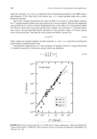
crack growth rate in a viscous material should depend only on the value of C*. Experimental studies
[45–49] have shown that creep crack growth rates correlate very well with C*, provided steady-
state creep is the dominant deformation mechanism in the specimen. Figure 4.18 shows typical
creep crack growth data. Note that the crack growth rate follows a power law:
˙ a ( γ C = ) * m (4.34)
where γ and m are material constants. In many materials, m ≈ n/(n + 1), a result that is predicted by
grain boundary cavitation models [49].
Experimental measurements of C* take advantage of analogies with the J integral. Recall that
J is usually measured by invoking the energy release rate definition:
∂
J =− 1 ∫ ∆ Pd (4.35)
∆
B a ∂ 0 ∆
FIGURE 4.18 Creep crack growth data in a Cr-Mo Steel at three temperatures. Taken from Riedel, H.,
“Creep Crack Growth.” ASTM STP 1020, American Society for Testing and Materials, Philadelphia, PA,
1989, pp. 101–126.