
Page 172 - From Smart Grid to Internet of Energy
P. 172
Power line communication technologies in smart grids Chapter 4 149
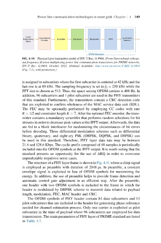
FIG. 4.10 Physical layer transmitter model of ITU-T Rec. G.9904. (From Narrowband orthogo-
nal frequency division multiplexing power line communication transceivers for PRIME networks,
ITU-T Rec. G.9904, October 2012. [Online] Available: http://www.itu.int/rec/T-REC-G.9904
(Fig. 7-1), with permission.)
is assigned to subcarriers where the first subcarrier is centered at 42 kHz and the
last one is at 89 kHz. The sampling frequency is set to f S ¼ 250 kHz while the
FFT size is chosen as 512. Thus, the space among OFDM carriers is 488 Hz. In
addition, 96 subcarriers and 1 pilot subcarrier are used in the PHY transmitters
of this standard. Furthermore, the transmitters contain a CRC detection code
that are exploited to confirm wholeness of the MAC service data unit (SDU).
The FEC may be optionally performed by employing CC codes with rate
R ¼ 1/2 and constraint length K ¼ 7. After the optional FEC encoder, the trans-
mitter contains a mandatory scrambler that performs random selections for bit
streams in order to decrease peak values at the IFFT output. Afterwards, the data
are fed to a block interleaver for randomizing the circumstances of bit errors
before decoding. Three differential modulation schemes such as differential
binary, quaternary, and eight-ary PSK (DBPSK, DQPSK, and D8PSK) can
be used in this standard. Therefore, PHY layer data rate may be between
21.4 and 128.6 Kbps. The cyclic prefix composed of 48 samples is periodically
included into the OFDM symbols at the IFFT output. It is worth noting that the
standard presents an opportunity for the use of ARQ in order to overcome
unpredictable impulsive noise cases.
The structure of a PHY layer frame is shown in Fig. 4.11 where a chirp signal
is employed as preamble with duration of 2048 μs. In preamble, a constant
envelope signal is exploited in lieu of OFDM symbols for maximizing the
energy. In addition, the use of preamble helps to provide frame detection and
automatic control gain adjustment in an efficient way. After the preamble,
one header with two OFDM symbols is included to the frame in which the
header is modulated by DBPSK scheme to transmit data related to payload
length, modulation, FEC, MAC header and CRC.
The OFDM symbols of PHY header contain 84 data subcarriers and 13
pilot subcarriers that are included to the header for generating phase reference
needed for channel estimation process. Only one carrier is exploited as pilot
subcarrier in the time of payload where 96 subcarriers are employed for data
transmission. The main parameters of PHY layer of PRIME standard are listed
in Table 4.7.