
Page 210 - Fundamentals of Communications Systems
P. 210
6.32 Chapter Six
G ( f )
m
1
−W W f
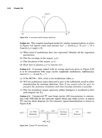
Figure 6.35 A message signal energy spectrum.
Problem 6.9. The complex baseband model for analog communications is given
in Figure 5.8. Ignore noise and assume m(t) = sin(2π f m t). If y z (t) = (5 +
3 sin(2π f m t)) exp[ j π/3],
(a) What kind of modulation does this represent? Identify all the important
parameters.
(b) Plot the envelope of the output, y A (t).
(c) Plot the phase of the output, y P (t).
(d) Show how to process y z (t) to recover m(t).
Problem 6.10. A message signal with an energy spectrum given in Figure 6.35
is to be transmitted with large carrier amplitude modulation. Additionally,
min(m(t)) =−2 and P m = 1.
(a) If the MCPR = 25%, what is the modulation index, a.
(b) Will the modulation index obtained in part (a) be sufficiently small to allow
demodulation by envelope detection. Note if you cannot solve for part (a)
just give the necessary conditions such that envelope detection is possible.
(c) Plot the modulator output spectrum (either bandpass or baseband is fine)
and compute the E B .
Problem 6.11. Commercial TV uses large carrier AM transmission in conjunc-
tion with VSB-AM for the intensity signal (black and white levels). A typical
TV receiver block diagram for the intensity signal demodulation is shown in
Figure 6.36.
xt () yt ()
z
z
m t () LC-VSB Envelope DC ˆ mt ()
Modulator Detector Remover
exp − [ jφ ] p
Figure 6.36 Typical TV demodulator.