
Page 101 - Fundamentals of Computational Geoscience Numerical Methods and Algorithms
P. 101
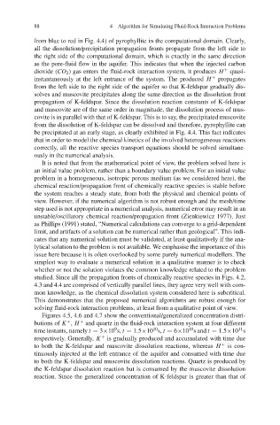
88                      4 Algorithm for Simulating Fluid-Rock Interaction Problems

            from blue to red in Fig. 4.4) of pyrophyllite in the computational domain. Clearly,
            all the dissolution/precipitation propagation fronts propagate from the left side to
            the right side of the computational domain, which is exactly in the same direction
            as the pore-fluid flow in the aquifer. This indicates that when the injected carbon
            dioxide (CO 2 ) gas enters the fluid-rock interaction system, it produces H  +  quasi-
            instantaneously at the left entrance of the system. The produced H  +  propagates
            from the left side to the right side of the aquifer so that K-feldspar gradually dis-
            solves and muscovite precipitates along the same direction as the dissolution front
            propagation of K-feldspar. Since the dissolution reaction constants of K-feldspar
            and muscovite are of the same order in magnitude, the dissolution process of mus-
            covite is in parallel with that of K-feldspar. This is to say, the precipitated muscovite
            from the dissolution of K-feldspar can be dissolved and therefore, pyrophyllite can
            be precipitated at an early stage, as clearly exhibited in Fig. 4.4. This fact indicates
            that in order to model the chemical kinetics of the involved heterogeneous reactions
            correctly, all the reactive species transport equations should be solved simultane-
            ously in the numerical analysis.
              It is noted that from the mathematical point of view, the problem solved here is
            an initial value problem, rather than a boundary value problem. For an initial value
            problem in a homogeneous, isotropic porous medium (as we considered here), the
            chemical reaction/propagation front of chemically reactive species is stable before
            the system reaches a steady state, from both the physical and chemical points of
            view. However, if the numerical algorithm is not robust enough and the mesh/time
            step used is not appropriate in a numerical analysis, numerical error may result in an
            unstable/oscillatory chemical reaction/propagation front (Zienkiewicz 1977). Just
            as Phillips (1991) stated, “Numerical calculations can converge to a grid-dependent
            limit, and artifacts of a solution can be numerical rather than geological”. This indi-
            cates that any numerical solution must be validated, at least qualitatively if the ana-
            lytical solution to the problem is not available. We emphasise the importance of this
            issue here because it is often overlooked by some purely numerical modellers. The
            simplest way to evaluate a numerical solution in a qualitative manner is to check
            whether or not the solution violates the common knowledge related to the problem
            studied. Since all the propagation fronts of chemically reactive species in Figs. 4.2,
            4.3 and 4.4 are comprised of vertically parallel lines, they agree very well with com-
            mon knowledge, as the chemical dissolution system considered here is subcritical.
            This demonstrates that the proposed numerical algorithms are robust enough for
            solving fluid-rock interaction problems, at least from a qualitative point of view.
              Figures 4.5, 4.6 and 4.7 show the conventional/generalized concentration distri-
            butions of K , H and quartz in the fluid-rock interaction system at four different
                          +
                      +
                                     9
                                                                            11
                                                            10
                                                 10
            time instants, namely t = 3×10 s, t = 1.5×10 s, t = 6×10 s and t = 1.5×10 s
            respectively. Generally, K  +  is gradually produced and accumulated with time due
            to both the K-feldspar and muscovite dissolution reactions, whereas H  +  is con-
            tinuously injected at the left entrance of the aquifer and consumed with time due
            to both the K-feldspar and muscovite dissolution reactions. Quartz is produced by
            the K-feldspar dissolution reaction but is consumed by the muscovite dissolution
            reaction. Since the generalized concentration of K-feldspar is greater than that of