
Page 168 - Fundamentals of Enhanced Oil and Gas Recovery
P. 168
156 Forough Ameli et al.
5.2.3.1 Description of the Method
In this method, air is injected to crude oil reservoir. After ignition, the generated heat
keeps the combustion front moving toward the production well. Combustion front
burns all the fuel in its way. Usually 5% 10% of the crude oil is used as a fuel and the
rest is going to be produced in the production well. The heat of reaction vaporizes
initial water and also the light components of oil at the advance of combustion front.
The steam is condensed while distancing from the hot region. This method is also
applicable for light oil reservoirs. The viscosity of the fluid would decrease which leads
to more recovery of the reservoir. Combustion causes decomposition of asphaltene
and other heavy fractions to lighter compounds, flue gases, and heat. A stable steam
front is generated as a result of water condensation that under-effects the crude oil
mobility. As the gases are miscible in oil, the process of miscible gas injection also
occurs.
5.2.4 Toe-to-Heel Air Injection
A newly developed thermal process in the category of ISC is called toe-to-heel air
injection (THAI). As in common ISC processes, the producer and injectors are verti-
cal, the sweeping efficiency is limited which is due to overrunning or channeling.
This problem is resolved by using horizontal producers or toe-to-heel well construc-
tion, to control the flow regime in the reservoir. This technology is applicable for two
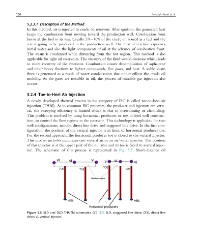
well configurations, namely, direct line drive and staggered line drive. In the first con-
figuration, the position of the vertical injector is in front of horizontal producer toe.
For the second approach, the horizontal producer toe is closed to the vertical injector.
This process includes minimum one vertical air or an air/water injector. The position
of this injector is at the upper part of the oil layer and its toe is faced to vertical injec-
tor. The schematic of this process is represented in Fig. 5.5. Short-distance oil
Figure 5.5 SLD and DLD THAITM schematics (VI) [37]. SLD, staggered line drive; DLD, direct line
drive; VI, vertical injector.