
Page 45 - Fundamentals of Enhanced Oil and Gas Recovery
P. 45
An Introduction to Enhanced Oil Recovery 33
1.15.2 Mobility Ratio Control Through EOR Process
1.15.2.1 Chemical Injection
In this method surfactant injection or in situ surfactant production through injecting
solution/crude oil causes oil to move. Because the polymer is expensive, a little bit of
it, approximately 4% 5% PV, is injected and then displaced by water.
Mobility control in the chemical process is carried out in three stages:
• Preventing the fingering of the chemical material with oil
• Mobility control between the chemical solution and the minimized chemical slug
• Preventing the fingering of water injection front with the polymer containing
chemical
1.15.2.2 Miscible Gas Injection
After one or more miscible contacts, since the viscosity of gas is much less than that
of the water or oil, the mobility ratio would not be suitable. In addition to reducing
sweep efficiency, this factor will also affect fingering and lead to the mobility of gas in
a space with high permeability.
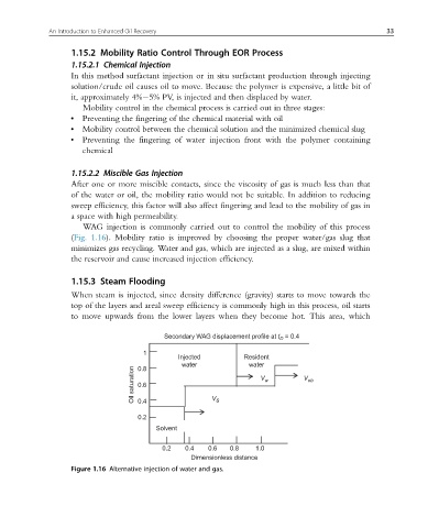
WAG injection is commonly carried out to control the mobility of this process
(Fig. 1.16). Mobility ratio is improved by choosing the proper water/gas slug that
minimizes gas recycling. Water and gas, which are injected as a slug, are mixed within
the reservoir and cause increased injection efficiency.
1.15.3 Steam Flooding
When steam is injected, since density difference (gravity) starts to move towards the
top of the layers and areal sweep efficiency is commonly high in this process, oil starts
to move upwards from the lower layers when they become hot. This area, which
Secondary WAG displacement profile at t = 0.4
D
1
Injected Resident
water water
Oil saturation 0.6 V V w V ob
0.8
0.4
0.2 s
Solvent
0.2 0.4 0.6 0.8 1.0
Dimensionless distance
Figure 1.16 Alternative injection of water and gas.