
Page 190 - Fundamentals of Gas Shale Reservoirs
P. 190
170 GEOMECHANICS OF GAS SHALES
these parameters on various applications during different
phases of a field life including exploration, drilling, and
completion.
8.2 MECHANICAL PROPERTIES OF GAS SHALE
RESERVOIRS
The characteristics of shales have been mainly studied on
many occasions as a seal or overpressure region (e.g.,
Dewhurst and Hennig, 2003; Dewhurst et al., 1998, 1999;
Yang and Aplin, 2007) or wellbore instability problematic
area (e.g., Detournay et al., 2006; Horsrud, 2001; Sarout and
Detournay, 2011). Many studies have also been conducted
on preventing pore pressure build up around the wellbore
caused by the shale–drilling fluids interaction (Bol and
Woodland, 1992; Ewy and Stankovich, 2000; Schlemmer
et al., 2002; Tare et al., 2000; Van Oort et al., 1995; Yu et al.,
2001). However, there is still limited information and
knowledge regarding the geomechanical parameters of gas
shale reservoirs.
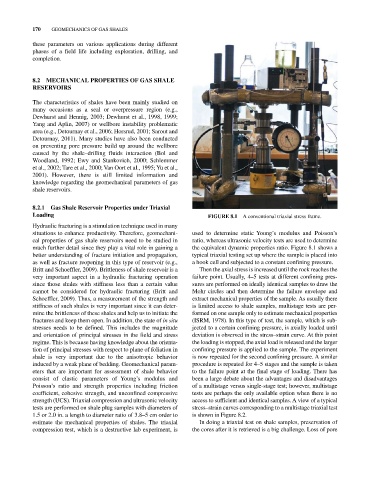
8.2.1 Gas Shale Reservoir Properties under Triaxial
Loading FIGURE 8.1 A conventional triaxial stress frame.
Hydraulic fracturing is a stimulation technique used in many
situations to enhance productivity. Therefore, geomechani used to determine static Young’s modulus and Poisson’s
cal properties of gas shale reservoirs need to be studied in ratio, whereas ultrasonic velocity tests are used to determine
much further detail since they play a vital role in gaining a the equivalent dynamic properties ratio. Figure 8.1 shows a
better understanding of fracture initiation and propagation, typical triaxial testing set up where the sample is placed into
as well as fracture reopening in this type of reservoir (e.g., a hook cell and subjected to a constant confining pressure.
Britt and Schoeffler, 2009). Brittleness of shale reservoir is a Then the axial stress is increased until the rock reaches the
very important aspect in a hydraulic fracturing operation failure point. Usually, 4–5 tests at different confining pres
since those shales with stiffness less than a certain value sures are performed on ideally identical samples to draw the
cannot be considered for hydraulic fracturing (Britt and Mohr circles and then determine the failure envelope and
Schoeffler, 2009). Thus, a measurement of the strength and extract mechanical properties of the sample. As usually there
stiffness of such shales is very important since it can deter is limited access to shale samples, multistage tests are per
mine the brittleness of these shales and help us to initiate the formed on one sample only to estimate mechanical properties
fractures and keep them open. In addition, the state of in situ (ISRM, 1978). In this type of test, the sample, which is sub
stresses needs to be defined. This includes the magnitude jected to a certain confining pressure, is axially loaded until
and orientation of principal stresses in the field and stress deviation is observed in the stress–strain curve. At this point
regime. This is because having knowledge about the orienta the loading is stopped, the axial load is released and the larger
tion of principal stresses with respect to plane of foliation in confining pressure is applied to the sample. The experiment
shale is very important due to the anisotropic behavior is now repeated for the second confining pressure. A similar
induced by a weak plane of bedding. Geomechanical param procedure is repeated for 4–5 stages and the sample is taken
eters that are important for assessment of shale behavior to the failure point at the final stage of loading. There has
consist of elastic parameters of Young’s modulus and been a large debate about the advantages and disadvantages
Poisson’s ratio and strength properties including friction of a multistage versus single‐stage test; however, multistage
coefficient, cohesive strength, and unconfined compressive tests are perhaps the only available option when there is no
strength (UCS). Triaxial compression and ultrasonic velocity access to sufficient and identical samples. A view of a typical
tests are performed on shale plug samples with diameters of stress–strain curves corresponding to a multistage triaxial test
1.5 or 2.0 in. a length to diameter ratio of 3.8–5 cm order to is shown in Figure 8.2.
estimate the mechanical properties of shales. The triaxial In doing a triaxial test on shale samples, preservation of
compression test, which is a destructive lab experiment, is the cores after it is retrieved is a big challenge. Loss of pore