
Page 198 - Fundamentals of Gas Shale Reservoirs
P. 198
178 GEOMECHANICS OF GAS SHALES
1 If there is a strong stress contrast between σ and σ ,
y
x
the above analysis typically holds true. However, for a
z' small stress contrast and within the sensitive borehole/
bedding orientation, other failures may occur, which
z depend on the degree of the weakness of the planes. Thus,
determination of a safe mud window and a safe direction
y
of drilling need to be carried out, taking into account the
above equations when directional drilling is planned in
formations containing weakness plane. It should be
x remembered that in anisotropic stress field, wells may be
stable for some azimuths, but fail under another drilling
direction; so critical parameters like planes of weakness,
y' 2 normal stress, and the angle between the borehole and
bedding plane should be calculated. Besides, it should be
noticed that for many bedded rocks, the critical angle
between borehole and bedding is 10–30°. For zero or 90°
the wells are more stable.
x'
8.4.2 Instability due to Directional Dependency
3 of Geomechanical Parameters
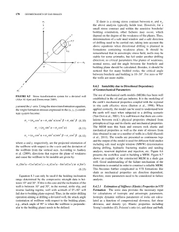
FIGURE 8.5 Stress transformation system for a deviated well The use of mechanical earth models (MEMs) has been well
(After Al‐Ajmi and Zimmerman 2009). established in the oil and gas industry. It is the modeling of
the earth’s mechanical properties coupled with the regional
γ around the y′‐axis. Using the stress transformation equation, in situ earth effective stress (Barton et al., 1998). When
the virgin formation stresses expressed in the (x, y, z) coordi applied correctly, the model can be used to understand how
nate system become: the earth will react when subjected to a drilling scenario
(Van Oort et al., 2001). It is well known that there are corre
( cos 2 sin 2 )cos 2 sin 2 (8.10) lations between rock’s physical properties obtained from
x H h v
petrophysical logs and its elastic and mechanical properties.
( sin 2 cos 2 ) (8.11) The MEM uses this basis and extracts rock elastic and
y H h mechanical properties as well as the state of stresses from
( cos 2 sin 2 )sin 2 cos 2 (8.12) data obtained in one or a number of wells in a field (Rasouli
z H h v et al., 2011). The results are presented as continuous logs
and the output of the model is used for different field studies
where α and γ, respectively, are the projected orientation of including safe mud weight window (MWW) determination
the wellbore with respect to the x‐axis and the deviation of during drilling, hydraulic fracturing studies and sanding
the wellbore from the vertical axis. According to Aadnoy analysis, reservoir depletion and injection, etc. Figure 8.6
et al. (2009), directions that expose the plane of weakness presents the workflow used in building a MEM. Figure 8.7
and cause the wellbore to be instable are given by:
shows an example of the constructed MEM in a shale gas
well. Good understanding of the failure mechanism of the
2
2
2
( Sin 2 Cos Cos ) ( Cos 2 Sin 2 Cos ) Sin 2
H h v formations is essential in order to construct a reliable MEM.
(8.13) This becomes further complicated in VTI formations like
shale as mechanical properties are direction dependent;
Equation 8.3 can only be used if the bedding inclination therefore, more parameters need to be considered in failure
range determined by the compressive strength data is bet analysis.
ween 10° and 30°. If this is the case and the inclination of the
well is between 10° and 30°, in the normal, strike slip, and 8.4.2.1 Estimation of Stiffness (Elastic) Properties in VTI
reverse faulting regime, well with azimuth of 0°–40° will Formation The sonic data provides the necessary input
fail due to bedding plane exposal. Thus, in the entire drilling for calculations of isotropic and anisotropic parameters.
operation aiming at drilling a deviated well, the attack angle Isotropic dynamic stiffness parameters of rocks are calcu
(orientation of wellbore with respect to the bedding plane, lated as a function of compressional slowness, fast shear
e.g., attack angle of 90° is when the wellbore is perpendic slowness, and density (ρ). Elastic properties including
ular to the bedding plane) needs to be defined. Young’s modulus (E), Poisson’s ratio (υ), and shear and bulk