
Page 199 - Fundamentals of Gas Shale Reservoirs
P. 199
WELLBORE INSTABILITY IN GAS SHALE RESERVOIRS 179
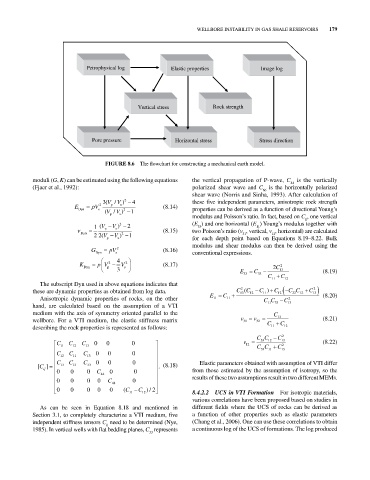
Petrophysical log Elastic properties Image log
Vertical stress Rock strength
Pore pressure Horizontal stress Stress direction
FIGURE 8.6 The flowchart for constructing a mechanical earth model.
moduli (G, K) can be estimated using the following equations the vertical propagation of P‐wave, C is the vertically
44
(Fjaer et al., 1992): polarized shear wave and C is the horizontally polarized
66
shear wave (Norris and Sinha, 1993). After calculation of
3( VV ) 2 4 these five independent parameters, anisotropic rock strength
/
E V 2 p s (8.14)
Dyn s ( VV ) 2 1 properties can be derived as a function of directional Young’s
/
p s modulus and Poisson’s ratio. In fact, based on C , one vertical
ij
1 (V p V s ) 2 2 (E ) and one horizontal (E ) Young’s modulus together with
11
33
Dyn 2 2(V V ) 2 1 (8.15) two Poisson’s ratio (v , vertical, v , horizontal) are calculated
31
12
p s for each depth point based on Equations 8.19–8.22. Bulk
modulus and shear modulus can then be derived using the
2
G Dyn pV s (8.16) conventional expressions.
4
K Dyn p V p 2 V s 2 (8.17) 2 C 2
3 E 33 C 33 13 (8.19)
C 11 C 12
The subscript Dyn used in above equations indicates that
2
these are dynamic properties as obtained from log data. CC ( 12 C ) C 12 CC 12 C 13 2
33
13
11
Anisotropic dynamic properties of rocks, on the other E 11 C 11 CC C 2 (8.20)
hand, are calculated based on the assumption of a VTI 11 33 13
medium with the axis of symmetry oriented parallel to the C
wellbore. For a VTI medium, the elastic stiffness matrix v 31 v 32 C 13 C (8.21)
describing the rock properties is represented as follows: 11 12
CC 12 C 13 2
33
C C C 0 0 0 v 12 (8.22)
11 12 13 CC C 2
C C C 0 0 0 33 11 13
12 11 13
C C C 0 0 0 Elastic parameters obtained with assumption of VTI differ
[C ij ] 13 13 33 . (8.18)
0 0 0 C 0 0 from those estimated by the assumption of isotropy, so the
44
0 0 0 0 C 0 results of these two assumptions result in two different MEMs.
44
0 0 0 0 0 0 (C 11 C 12 ) 2 / 8.4.2.2 UCS in VTI Formation For isotropic materials,
various correlations have been proposed based on studies in
As can be seen in Equation 8.18 and mentioned in different fields where the UCS of rocks can be derived as
Section 3.1, to completely characterize a VTI medium, five a function of other properties such as elastic parameters
independent stiffness tensors C need to be determined (Nye, (Chang et al., 2006). One can use these correlations to obtain
ij
1985). In vertical wells with flat bedding planes, C represents a continuous log of the UCS of formations. The log produced
33