
Page 293 - Fundamentals of Gas Shale Reservoirs
P. 293
CAPILLARY PRESSURE, RELAXATION TO EQUILIBRIUM STATE, AND DEPOSITION OF STIMULATION WATER 273
1.0 porosity, permeability, relative permeability, and capillary
pressure curves were chosen to be consistent with the then
0.9 understanding of shale gas reservoirs, and with each other. A
range of values for the parameters was investigated. The
k Ga /k G0 0.8 modeling was performed with a commercial simulator by
assuming the stimulation fracture system was filled with
0.7 water at a prescribed pressure, and then leak off and produc
tion was simulated. During the leak off, the well was being
0.6 produced. Because of the high capillary pressures, and the
0 2500 5000 gas being stored in water wet pores, essentially no water
Pore pressure (psia) was produced. Countercurrent imbibition drove the frac
water into the gas bearing pores and the gas into the
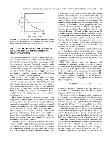
FIGURE 12.3 The geometrical permeability for adsorbing pores fractures. The observation that much more water is pro
at 5000 psia is reduced to 62% of the value it would have without duced than would be predicted by the simulation is a strong
adsorption (modified after Fig. 7 in Sigal, 2013b).
argument, and the pores where gas is stored in shale gas
reservoirs are generally not water wet.
12.5 CAPILLARY PRESSURE, RELAXATION TO In the formation of the stimulation fracture system, water
EQUILIBRIUM STATE, AND DEPOSITION OF may be forced into fractures that then become disconnected
STIMULATION WATER from the rest of the fracture system trapping water. If this
accounted for the large majority of the lost frac water, then
Because of the nanometer‐scale pores in organic shale reser most of the created fracture system ends up ineffective for
voirs, capillary forces can produce pressure differences aiding gas production.
between the wetting and nonwetting phases comparable to Most shale reservoirs have been stimulated with
the in situ reservoir pressure. These small pores also greatly freshwater, but the reservoir salinity is certainly at least that
diminish the rate at which fluid saturations can adjust when of seawater and may be much higher due to water vapor
fluid pressure is changed. Under these conditions, the normal being removed by the expulsion of oil and gas from the res
assumption that the wetting and nonwetting phase pressures ervoir over geologic time. A regression relationship, the Hill
are related by a capillary pressure curve established for Shirley Kline equation, developed by Shell researchers (Hill
equilibrium saturation states breaks down. et al., 1979) provides a relationship between the amount of
This would not be a significant issue if one could clay‐bound water and the clay type and the water salinity.
assume immobile water and only simulate gas flow. These The equation reads
reservoirs though are massively hydraulically fractured
.
.
which could put mobile water into the system. Only a Ws 0 084 C o 5 022 CEC (12.28)
fraction of the stimulation water normally flows back, and
much of that is more saline than the initial frac water. where Ws is the clay‐bound water in g/100 g of dry clay, C
o
Thus, understanding the deposition of this water is impor the salinity in equivalents/l, and CEC the clay cation‐
tant both for reservoir management and to answer environ exchange capacity in meq/100 g.
mental concerns. The equation shows that the amount of clay‐bound water
There are multiple possible reasons for water used in frac held by a clay system increases significantly when the water
turing not being returned to the surface. Among the reservoir salinity is reduced as would happen near the fracture face
conditions that control this are reservoir rock wettability, with fresh frac water and a high salinity reservoir. Over long‐
types and saturation of clays, presence and types of natural time periods, diffusion will cause a redistribution of this
fractures, the final connectivity of the stimulation fracture additional clay‐bound water as the salinity in the reservoir
system, reservoir salinity, reservoir gas pressure, and the comes to equilibrium. The exact amount of frac water immo
nature of pores, where the gas is stored in. There is poor bilized by this mechanism depends on the amount of clay
quantitative understanding of the effects these conditions and the clay types, fracture face surface area, the perme
have on the amounts of frac fluid returned. Some of the con ability of the clay zones, and the salinity and the effective
ditions result in the frac water being immobile and some may CEC. Most of these factors are at best poorly known. Clay
leave mobile water in the formation. amounts and types can be reasonably well established from
Qin (2007) studied the deposition of fracture water from a core and/or log measurements. Reservoir salinity may be
vertical well with a simple multibranched fracture system. The known. If cation exchange capacity (CRC) values are
reservoirs simulated were low permeability, low porosity gas known for the clay types, they generally vary by factors of
reservoirs that were assumed to be water wetting. They had an two for a given type. Some reservoirs have a significant
initial water saturation that allowed limited water mobility. The amount of mixed layer clays. Their CEC values are not