
Page 103 - Fundamentals of Light Microscopy and Electronic Imaging
P. 103
86 DIFFRACTION AND SPATIAL RESOLUTION
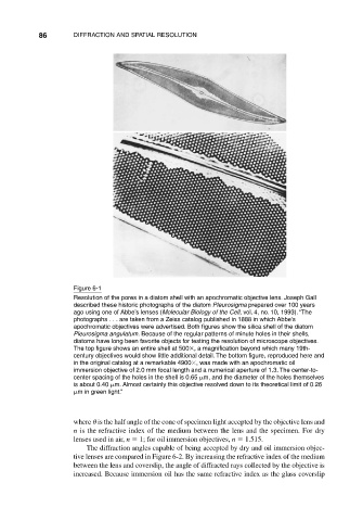
Figure 6-1
Resolution of the pores in a diatom shell with an apochromatic objective lens. Joseph Gall
described these historic photographs of the diatom Pleurosigma prepared over 100 years
ago using one of Abbe’s lenses (Molecular Biology of the Cell, vol. 4, no. 10, 1993). “The
photographs . . . are taken from a Zeiss catalog published in 1888 in which Abbe’s
apochromatic objectives were advertised. Both figures show the silica shell of the diatom
Pleurosigma angulatum. Because of the regular patterns of minute holes in their shells,
diatoms have long been favorite objects for testing the resolution of microscope objectives.
The top figure shows an entire shell at 500 , a magnification beyond which many 19th-
century objectives would show little additional detail. The bottom figure, reproduced here and
in the original catalog at a remarkable 4900 , was made with an apochromatic oil
immersion objective of 2.0 mm focal length and a numerical aperture of 1.3. The center-to-
center spacing of the holes in the shell is 0.65 m, and the diameter of the holes themselves
is about 0.40 m. Almost certainly this objective resolved down to its theoretical limit of 0.26
m in green light.”
where is the half angle of the cone of specimen light accepted by the objective lens and
n is the refractive index of the medium between the lens and the specimen. For dry
lenses used in air, n 1; for oil immersion objectives, n 1.515.
The diffraction angles capable of being accepted by dry and oil immersion objec-
tive lenses are compared in Figure 6-2. By increasing the refractive index of the medium
between the lens and coverslip, the angle of diffracted rays collected by the objective is
increased. Because immersion oil has the same refractive index as the glass coverslip