
Page 98 - Fundamentals of Light Microscopy and Electronic Imaging
P. 98
DIFFRACTION PATTERN FORMATION IN THE BACK APERTURE 81
objective’s back (or rear) focal plane. You should take a moment to reinspect the figures
in Chapter 1 and recall that this plane is conjugate with other aperture planes in the
microscope—that is, the lamp filament, the front focal plane of the condenser, and the
iris aperture of the eye. For specimens having periodic details (a diffraction grating) and
under certain conditions of diaphragm adjustments, you can inspect the diffraction pat-
tern of an object using a Bertrand lens. The diffraction pattern in the back aperture and
the image in the image plane are called inverse transforms of each other, since distance
relations among objects seen in one plane are reciprocally related to spacings present in
the other plane, as will now be explained.
Demonstration: Observing the Diffraction Image in the Back
Focal Plane of a Lens.
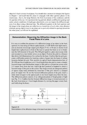
It is easy to confirm the presence of a diffraction image of an object in the back
aperture of a lens using an I-beam optical bench, a 3 mW HeNe laser light source,
and an electron microscope copper grid (Figure 5-16). A 50 mm or shorter focal
length lens is placed just in front of the laser to spread the beam so as to illumi-
nate the full diameter of the grid. The EM grid taped to a glass microscope slide
and mounted on a lens holder serves as an object. Position the grid at a distance
that allows full illumination of its surface by the laser. Confirm that the grid gen-
erates a diffraction pattern by inserting a piece of paper into the beam at various
locations behind the grid. Now position an optical bench demonstration lens of
50–100 mm focal length just over 1 focal length from the grid to create a sharply
focused image (real intermediate image) of the grid on a projection screen some
2–3 meters away from the lens. Adjust the lens position as required to obtain a
focused image of the grid on the screen. The image reveals an orthogonal pattern
of square empty holes delimited by metal bars of the grid, which is a stamped
piece of copper foil. To see the focused diffraction pattern of the grid, insert a
white sheet of paper in the optical path at one focal length away from the lens.
The diffraction pattern consists of an orthogonal pattern of bright points of light
(see Fig. 5-1). Confirm that the focused diffraction image is located precisely in
the back focal plane at 1 focal length distance by moving the paper screen back
and forth along the beam.
100 mm f.l.
50 mm f.l. lens
lens (objective)
3 27 11 15 83
Laser Grid Diffraction Image
(specimen) plane plane
Figure 5-16
Demonstration of the diffraction image in the back focal plane of a lens.