
Page 93 - Fundamentals of Light Microscopy and Electronic Imaging
P. 93
76 DIFFRACTION AND INTERFERENCE IN IMAGE FORMATION
+ 2 nd
Collimated
beam + 1 st
+ 0 th
– 1 st
Lamp
Mask IR filter Grating
Aperture
+ 2 nd
Screen
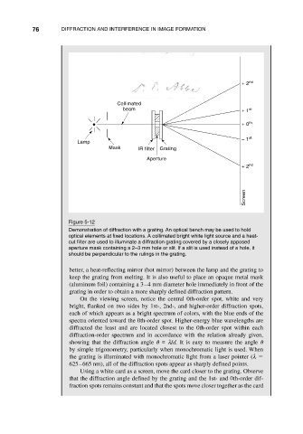
Figure 5-12
Demonstration of diffraction with a grating. An optical bench may be used to hold
optical elements at fixed locations. A collimated bright white light source and a heat-
cut filter are used to illuminate a diffraction grating covered by a closely apposed
aperture mask containing a 2–3 mm hole or slit. If a slit is used instead of a hole, it
should be perpendicular to the rulings in the grating.
better, a heat-reflecting mirror (hot mirror) between the lamp and the grating to
keep the grating from melting. It is also useful to place an opaque metal mask
(aluminum foil) containing a 3–4 mm diameter hole immediately in front of the
grating in order to obtain a more sharply defined diffraction pattern.
On the viewing screen, notice the central 0th-order spot, white and very
bright, flanked on two sides by 1st-, 2nd-, and higher-order diffraction spots,
each of which appears as a bright spectrum of colors, with the blue ends of the
spectra oriented toward the 0th-order spot. Higher-energy blue wavelengths are
diffracted the least and are located closest to the 0th-order spot within each
diffraction-order spectrum and in accordance with the relation already given,
showing that the diffraction angle λ/d. It is easy to measure the angle
by simple trigonometry, particularly when monochromatic light is used. When
the grating is illuminated with monochromatic light from a laser pointer (λ
625–665 nm), all of the diffraction spots appear as sharply defined points.
Using a white card as a screen, move the card closer to the grating. Observe
that the diffraction angle defined by the grating and the 1st- and 0th-order dif-
fraction spots remains constant and that the spots move closer together as the card