
Page 92 - Fundamentals of Light Microscopy and Electronic Imaging
P. 92
DIFFRACTION BY A GRATING AND CALCULATION OF ITS LINE SPACING, D 75
0th order
1st order
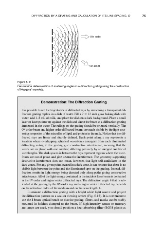
Figure 5-11
Geometrical determination of scattering angles in a diffraction grating using the construction
of Huygens’ wavelets.
Demonstration:The Diffraction Grating
It is possible to see the trajectories of diffracted rays by immersing a transparent dif-
fraction grating replica in a dish of water. Fill a 9 12 inch glass baking dish with
water, add 1–2 mL of milk, and place the dish on a dark background. Place a small
laser or laser pointer up against the dish and direct the beam at a diffraction grating
immersed in the water. The rulings on the grating should be oriented vertically. The
0 -order beam and higher order diffracted beams are made visible by the light-scat-
th
tering properties of the miscelles of lipid and protein in the milk. Notice that the dif-
fracted rays are linear and sharply defined. Each point along a ray represents a
location where overlapping spherical wavefronts emergent from each illuminated
diffracting ruling in the grating give constructive interference, meaning that the
waves are in phase with one another, differing precisely by an integral number of
wavelengths. The dark spaces in between the rays represent regions where the wave-
fronts are out of phase and give destructive interference. The geometry supporting
destructive interference does not mean, however, that light self-annihilates in the
dark zones. For any given point located in a dark zone, it can be seen that there is no
visible light between the point and the illuminated spot on the grating. Instead, dif-
fraction results in light energy being directed only along paths giving constructive
interference. All of the light energy contained in the incident laser beam is contained
in the 0 order and higher order diffracted rays. The diffraction angle that is sub-
th
th
tended at the grating by the 0 -order ray and a higher order diffracted ray depends
on the refractive index of the medium and on the wavelength, .
Illuminate a diffraction grating with a bright white light source and project
the diffraction pattern on a wall or viewing screen (Fig. 5-12). It is convenient to
use the I-beam optical bench so that the grating, filters, and masks can be stably
mounted in holders clamped to the beam. If high-intensity xenon or mercury
arc lamps are used, you should position a heat-absorbing filter (BG38 glass) or,