
Page 89 - Fundamentals of Light Microscopy and Electronic Imaging
P. 89
72 DIFFRACTION AND INTERFERENCE IN IMAGE FORMATION
+3 rd
+2 nd
+1 st
Collimated beam
0 th
Grating – 1 st
– 2 rd
– 3 rd
Screen
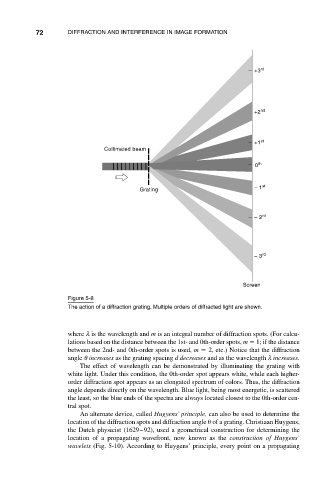
Figure 5-8
The action of a diffraction grating. Multiple orders of diffracted light are shown.
where λ is the wavelength and m is an integral number of diffraction spots. (For calcu-
lations based on the distance between the 1st- and 0th-order spots, m 1; if the distance
between the 2nd- and 0th-order spots is used, m 2, etc.) Notice that the diffraction
angle increases as the grating spacing d decreases and as the wavelength λ increases.
The effect of wavelength can be demonstrated by illuminating the grating with
white light. Under this condition, the 0th-order spot appears white, while each higher-
order diffraction spot appears as an elongated spectrum of colors. Thus, the diffraction
angle depends directly on the wavelength. Blue light, being most energetic, is scattered
the least, so the blue ends of the spectra are always located closest to the 0th-order cen-
tral spot.
An alternate device, called Hugyens’ principle, can also be used to determine the
location of the diffraction spots and diffraction angle of a grating. Christiaan Huygens,
the Dutch physicist (1629–92), used a geometrical construction for determining the
location of a propagating wavefront, now known as the construction of Huygens’
wavelets (Fig. 5-10). According to Huygens’ principle, every point on a propagating