
Page 163 - Fundamentals of Light Microscopy and Electronic Imaging
P. 163
146 POLARIZATION MICROSCOPY
45°
Random Linear Circular Linear
Blocked
(a)
45°
Transmitted
Polarizer Object /4 plate Analyzer
(b)
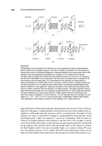
Figure 9-6
Compensation by the method of de Sénarmont. The equipment includes a fixed polarizer
and /4-plate and a rotatable analyzer. The fixed /4-plate is inserted in the microscope so
that the slow axis of its wavefront ellipsoid is oriented parallel to the transmission axis of the
analyzer when the polarizer and analyzer are crossed. A /4-compensator produces
circularly polarized light from incident linearly polarized waves and vice versa. To measure
the amount of retardation from a specimen, the slow axis of the specimen is oriented at 45°
with respect to the crossed polars. For convenience in the drawing, an object giving a
relative retardation of /4 (the same as the /4-plate) is shown; hence, emergent waves are
circularly polarized. The /4-plate converts these waves into linearly polarized light whose
plane of vibration is now tipped 45° relative to the plane of the initial wave produced by the
polarizer. When examined with the analyzer in crossed position, the object appears medium
gray. Rotating the analyzer from its 0 position counterclockwise 45° blocks light transmission
and gives extinction (a), while a clockwise 45° rotation gives maximum transmission (b).
Since the relative retardation by this method 2 , we calculate that the retardation by the
object is 2 45° 90°, or /4. In a more typical case, a birefringent cellular object giving
/20 retardation would require a rotation of the analyzer of 9° to give extinction.
plane of the plate. When inserted into the optical pathway, the slow axis of the wavefront
ellipsoid of the plate is oriented parallel to the transmission axis of the analyzer (the ori-
entation is north-south when the analyzer is in the crossed position). The plate is fixed
and does not rotate. As described in Chapter 8, a plane-polarized beam incident on the
birefringent plate is split into separate O- and E-ray components. With the plane of
vibration of incident polarized waves parallel to the slow axis of the /4 plate, O and E
waves from background regions in the specimen emerge linearly polarized, are blocked
by the analyzer, and cause the field to look maximally dark. As the analyzer is rotated,
the field brightens until it becomes maximally bright at an analyzer setting 90° away
from that giving extinction. At 45° rotation, the field looks medium gray. Colors are not
observed with incident white light because the amount of retardation introduced is con-