
Page 331 - Fundamentals of Light Microscopy and Electronic Imaging
P. 331
314 IMAGE PROCESSING FOR SCIENTIFIC PUBLICATION
and offset separately for each fluorescence signal (background 0, saturation 255) so
that each fluorochrome is displayed using a full 0–255 gray-scale range (objective, easy
to do, and easy to explain and describe to others). The images are then processed if nec-
essary and merged. This is a conventional way to acquire and display multicolor images;
however, because each signal is acquired to fill the gray-scale range, this method does not
allow you to determine the relative amplitudes of the two signals in the original speci-
men, only the relative signal strength within a given color channel.
In a perfectly aligned fluorescence imaging system, a point source in the specimen
is perfectly registered, pixel for pixel, by different filter sets at the image plane in the
camera. However, inadequate color correction of the objective lens or poorly aligned fil-
ters can cause misregistration of fluorescence signals during color merging. This artifact
is recognizable by the uniform displacement of signals. In images with complex patterns
and a mixture of bright and dim signals, this can go undetected, leading you to conclude
that signal distribution in a structure is distinct or partially overlapping. Therefore, dur-
ing a color merge operation, in order to obtain good registration, it is important to be
able to freely move the color layers with respect to each other, an operation called pan-
ning. The ability to align through panning requires the presence of coincident reference
points (prominent features in the object) in each color layer. If multiply stained refer-
ence points do not exist, it may be useful to add multifluorescent beads to the specimen,
at a dilution giving just a few beads per field of view, prior to mounting with a cover-
glass. For critical applications, there is another solution: Use a single multifluorescence
filter cube with a multiple-bandpass dichroic mirror and a barrier filter together with dif-
ferent fluorochrome-specific exciter filters so that the same dichroic mirror is used for
all of the fluorescence signals; this configuration is used in confocal microscopes and
other wide-field fluorescence microscopes where color alignment is critical.
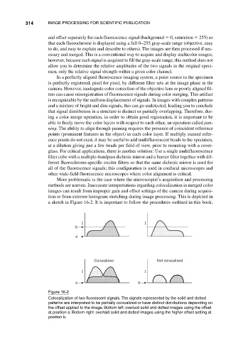
More problematic is the case where the microscopist’s acquisition and processing
methods are uneven. Inaccurate interpretations regarding colocalization in merged color
images can result from improper gain and offset settings of the camera during acquisi-
tion or from extreme histogram stretching during image processing. This is depicted in
a sketch in Figure 16-2. It is important to follow the procedures outlined in this book;
I I
b
a
Colocalized Not colocalized
I I
a b
Figure 16-2
Colocalization of two fluorescent signals. The signals represented by the solid and dotted
patterns are interpreted to be partially colocalized or have distinct distributions depending on
the offset applied to the image. Bottom left: overlaid solid and dotted images using the offset
at position a. Bottom right: overlaid solid and dotted images using the higher offset setting at
position b.