
Page 155 - Fundamentals of Magnetic Thermonuclear Reactor Design
P. 155
136 Fundamentals of Magnetic Thermonuclear Reactor Design
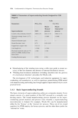
TABLE 5.7 Parameters of Superconducting Strands Designed for ITER
Magnets
Coils
Parameters PFCs, CCs CS, TFCs
Nb 3 Sn Nb 3 Sn
‘Bronze’ ‘Internal tin’
Superconductor NbTi process process
2
Current critical density (A/mm ) 2900 (5 T) 850 (12 T) 1000 (12 T)
Hysteresis energy losses (±3 T), — <1000 <1000
3
(mJ/cm )
Filament diameter (µm) 6–8 — —
Strand diameter (mm) 0.73 0.82–0.83
Copper/non-copper ratio 1.6–2.3 1
Unit length (m) >1500 >1500
Electrical resistivity ratio at 273 >100 >100
and 4.2 K (RRR, residual resis-
tance ratio)
Coating thickness (µm) 2 (Ni) 2 (Cr)
l Manufacturing of the winding turns using a roller-type guide to ensure ac-
curacy of the turn diameter and absence of internal mechanical stresses.
l ‘Winding–heat treatment–insulation rewinding (insertion into the grooves
of a mechanical structure)’ procedure for Nb Sn coils.
3
The development of SC technologies and industrial equipment for super-
conducting coil manufacture, as well as experience gained during ITER model
coils manufacturing and testing, has brought applied superconductivity to a new
practical level.
5.4.3 Basic Superconducting Strands
The basic elements of superconducting cables are composite strands. Every
strand consists of a great number of thin SCF encased in a normally con-
ducting matrix. The strand manufacturing process depends on the super-
conducting parent material and process route whereby a superconducting
microstructure is formed. For example, Nb Sn SCs can be manufactured
3
either by the ‘bronze’ or the ‘internal tin’ process. Three out of six strand
suppliers for ITER employ the bronze process, and the other three prefer the
‘internal tin’ route.