
Page 180 - Fundamentals of Magnetic Thermonuclear Reactor Design
P. 180
Superconducting Magnet Systems Chapter | 5 161
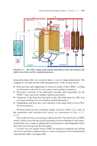
FIGURE A.5.1 The CSMC cooling circuit, position and numbers of the coil conductors and
radial cross-sections used for computation purposes.
temperature/mass flow rate occurred under a series of trapezoidal pulses. The
comparison was done for the following parameters of the cooling circuit:
l Peak pressure and temperature at reference points of the CSMC’s cooling
circuit points at the end of every current pulse (global parameters).
l Post-pulse evolution of the inlet/outlet pressure and temperature for the
CSMC’s inner and outer modules (global parameters).
l Variations of the heat load deposited in the LHe bath from two SHe heat
exchangers during each current pulse (global parameters).
l Temperature and mass flow rate variations at the inlet/outlet of each CICC
(local parameters).
Without going into the modelling details, reported in Ref. [22], some of
the experiment and simulation key results are summarised in Figs A.5.2–
A.5.8.
The results provide a convincing evidence that the Vincenta/Venecia CSMC
model is able to provide the desired agreement between theoretical and experi-
mental data over a range of global and local parameters and adequately reflect
their behaviour during and after the pulses.
As there were no sensors in the CSMC test program to measure the helium
mass flow rate at the conductor outlets, a direct comparison of the simulated and
experimental values was impossible.