
Page 184 - Fundamentals of Magnetic Thermonuclear Reactor Design
P. 184
Superconducting Magnet Systems Chapter | 5 165
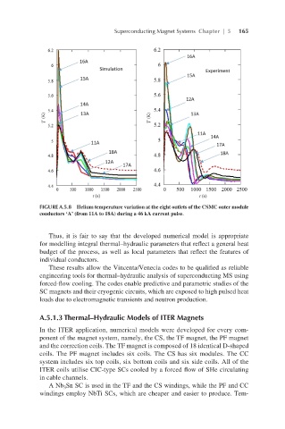
FIGURE A.5.8 Helium temperature variation at the eight outlets of the CSMC outer module
conductors ‘A’ (from 11A to 18A) during a 46 kA current pulse.
Thus, it is fair to say that the developed numerical model is appropriate
for modelling integral thermal–hydraulic parameters that reflect a general heat
budget of the process, as well as local parameters that reflect the features of
individual conductors.
These results allow the Vincenta/Venecia codes to be qualified as reliable
engineering tools for thermal–hydraulic analysis of superconducting MS using
forced-flow cooling. The codes enable predictive and parametric studies of the
SC magnets and their cryogenic circuits, which are exposed to high pulsed heat
loads due to electromagnetic transients and neutron production.
A.5.1.3 Thermal–Hydraulic Models of ITER Magnets
In the ITER application, numerical models were developed for every com-
ponent of the magnet system, namely, the CS, the TF magnet, the PF magnet
and the correction coils. The TF magnet is composed of 18 identical D-shaped
coils. The PF magnet includes six coils. The CS has six modules. The CC
system includes six top coils, six bottom coils and six side coils. All of the
ITER coils utilise CIC-type SCs cooled by a forced flow of SHe circulating
in cable channels.
A Nb Sn SC is used in the TF and the CS windings, while the PF and CC
3
windings employ NbTi SCs, which are cheaper and easier to produce. Tem-