
Page 187 - Fundamentals of Magnetic Thermonuclear Reactor Design
P. 187
168 Fundamentals of Magnetic Thermonuclear Reactor Design
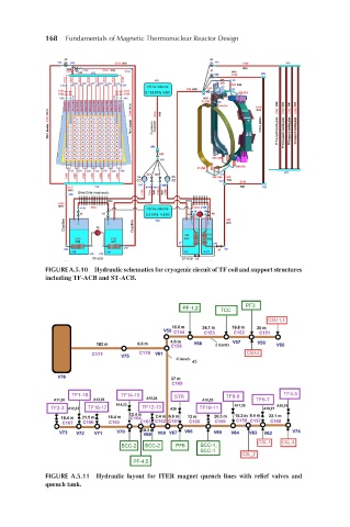
FIGURE A.5.10 Hydraulic schematics for cryogenic circuit of TF coil and support structures
including TF-ACB and ST-ACB.
FIGURE A.5.11 Hydraulic layout for ITER magnet quench lines with relief valves and
quench tank.