
Page 188 - Fundamentals of Magnetic Thermonuclear Reactor Design
P. 188
Superconducting Magnet Systems Chapter | 5 169
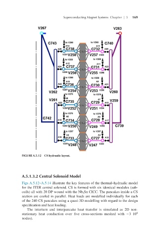
FIGURE A.5.12 CS hydraulic layout.
A.5.1.3.2 Central Solenoid Model
Figs A.5.12–A.5.14 illustrate the key features of the thermal–hydraulic model
for the ITER central solenoid. CS is formed with six identical modules (sub-
coils) all with 20 DP wound with the Nb Sn CICC. The pancakes inside a CS
3
section are cooled in parallel. Heat loads are modelled individually for each
of the 240 CS pancakes using a quasi-3D modelling with regard to the design
specification and heat loading.
The interturn and interpancake heat transfer is simulated as 2D non-
6
stationary heat conduction over five cross-sections meshed with ∼3 10
nodes).