
Page 193 - Fundamentals of Magnetic Thermonuclear Reactor Design
P. 193
174 Fundamentals of Magnetic Thermonuclear Reactor Design
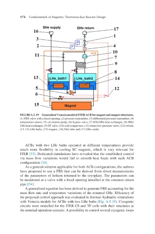
FIGURE A.5.19 Generalised Venecia model of ITER ACB for magnet and magnet structures.
(1) FBS valve with a fixed opening, (2) pressure transmitter, (3) differential pressure transmitter, (4)
temperature sensor, (5) circulation pump, (6) bypass valve, (7) SHe/GHe heat exchanger, (8) SHe/
LHe heat exchanger, (9) JT valve, (10) cold compressor, (11) return low-pressure valve, (12) switch,
(13, 14) LHe baths, (15) magnet, (16) SHe inlet and (17) GHe outlet.
ACBs with two LHe baths operated at different temperatures provide
much more flexibility in cooling SC magnets, which is very relevant for
ITER [33]. Dedicated simulations have revealed that the established control
via mass flow variations would fail to smooth heat loads with such ACB
configuration [34].
As a general solution applicable for both ACB configurations, the authors
have proposed to use a FBS that can be derived from direct measurements
of the parameters of helium returned to the cryoplant. The parameters can
be monitored at a valve with a fixed opening installed at the common return
pipe [34].
A generalised equation has been derived to generate FBS accounting for the
mass flow rate and temperature variations of the returned GHe. Efficiency of
the proposed control approach was evaluated in thermal–hydraulic simulations
with Venecia models for ACBs with two LHe baths (Fig. A.5.19). Cryogenic
circuits were modelled for the ITER CS and TF coils with their structures at
the nominal operation scenario. A possibility to control several cryogenic loops