
Page 189 - Fundamentals of Magnetic Thermonuclear Reactor Design
P. 189
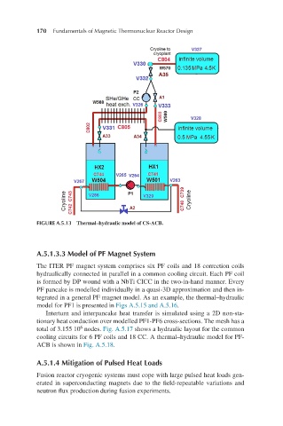
170     Fundamentals of Magnetic Thermonuclear Reactor Design


            FIGURE A.5.13  Thermal–hydraulic model of CS-ACB.


            A.5.1.3.3 Model of PF Magnet System

            The ITER PF magnet system comprises six PF coils and 18 correction coils
            hydraulically connected in parallel in a common cooling circuit. Each PF coil
            is formed by DP wound with a NbTi CICC in the two-in-hand manner. Every
            PF pancake is modelled individually in a quasi-3D approximation and then in-
            tegrated in a general PF magnet model. As an example, the thermal–hydraulic
            model for PF1 is presented in Figs A.5.15 and A.5.16.
               Interturn and interpancake heat transfer is simulated using a 2D non-sta-
            tionary heat conduction over modelled PF1-PF6 cross-sections. The mesh has a
                         6
            total of 3.155 10  nodes. Fig. A.5.17 shows a hydraulic layout for the common
            cooling circuits for 6 PF coils and 18 CC. A thermal–hydraulic model for PF-
            ACB is shown in Fig. A.5.18.

            A.5.1.4 Mitigation of Pulsed Heat Loads

            Fusion reactor cryogenic systems must cope with large pulsed heat loads gen-
            erated in superconducting magnets due to the field-repeatable variations and
            neutron flux production during fusion experiments.