
Page 186 - Fundamentals of Magnetic Thermonuclear Reactor Design
P. 186
Superconducting Magnet Systems Chapter | 5 167
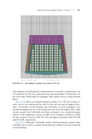
FIGURE A.5.9 2D meshing for median cross-section of TF coil.
The channels are hydraulically connected into two parallel cooling loops: one
(34 channels) for the inner, plasma-facing side and another (40 channels) for
the outer sides. Both loops are equipped with control valves to adjust helium
flows.
Fig. A.5.10 shows an integral hydraulic model of two TF coil cooling cir-
cuits: one for the winding and the other for the coil case and the support struc-
tures. A hydraulic circuit including four LHe baths, six heat exchangers, two
circulation pumps and two cold compressors has been developed. Part of this
circuit, namely, four LHe baths, five heat exchangers, two circulation pumps
and two cold compressors, forms a model of two auxiliary cold boxes (ACB)
for the cryogenic circuits of the TF coils and support structures (the TF-ACB
and ST-ACB, respectively).
Fig. A.5.11 illustrates a hydraulic model, which incorporates quench lines
and relief valves used to evacuate helium from the cooling circuit at coil quench
or fast discharge.