
Page 308 - Fundamentals of Magnetic Thermonuclear Reactor Design
P. 308
288 Fundamentals of Magnetic Thermonuclear Reactor Design
around 52%. A power reduction to 0.85 MW enabled the working cycle to be
extended to 203 s at an efficiency of 48%. Experiments proved that the station-
ary power can be increased to 2 MW at an efficiency of up to 70%.
Going forward, gyrotron systems could be improved in the following ways:
l Transition to modes of operation enabling recovery of the residual electron
energy to enhance the energy conversion efficiency and reduce the require-
ments for the power supply sources and the cooling system.
l Development of megawatt devices with a stepwise frequency tuning ability
to enhance the ECR heating efficiency and simplify the systems of antennas.
9.3.3 Ion Cyclotron Resonance Heating
In this plasma heating option, the power generator’s frequency must be the same
as the ion-cyclotron frequency
⋅
–1
08
wci≍1 ⋅Zi⋅Bt/Ai[s−1,T], ω ≈10 8 ⋅ ZB A [s ,T],
t
ci
i
i
where Z is the ion charge and A is the ion/proton mass ratio. For example,
i
i
in ITER, resonance frequencies for deuterium (Z = 1, A = 2) and helium-3
i
i
−1
8
8
−1
(Z = 2, A = 3) are 2.7 × 10 s and 3.5 × 10 s , respectively. Assuming
i
i
8 −1
w = 3 × 10 s , we obtain f ≈ 50 MHz, and λ ≈ 6 m. At such a wavelength,
ci
ci
ci
antenna elements for delivery of high-frequency power to the plasma should
be located inside the chamber [7]. Therefore, the antennas are exposed to radi-
ation—a feature that should be treated as a significant disadvantage. The rela-
tively simple design and low cost are undisputable strengths of such generators.
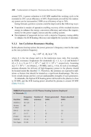
In tokamaks, the highest ICR heating power delivered to the plasma is close
to 30 MW, and the ICR heating power absorbed by plasma is around 20 MW
(Table 9.4) [5].
TABLE 9.4 Parameters of ICR Plasma Heating Systems Employed
in Tokamaks [5]
Frequency Number of Power generated Power absorbed
Machine (MHz) antennas (MW) (MW)
ASDEX-U 30–120 4 8 4
Alcator 80 2 4 3.5
C-Mod
DIII-D 30–120 3 6 3.6
JET 23–57 4 32 22
JT-60U 102–131 2 8 7
TEXTOR 25–38 2 4 3.6
Tore Supra 35–80 3 14 9.5