
Page 309 - Fundamentals of Magnetic Thermonuclear Reactor Design
P. 309
Plasma Heating Systems Chapter | 9 289
ICR heating systems include power generators, transmission lines and in-
chamber antennas. Powerful tetrodes act as generating tubes. The transmission
lines are located in the vacuum vessel ports. Loop antennas are typically used
for ICR plasma heating in tokamaks currently in operation. Travelling-wave
antennas are believed to be promising for ITER [8, 9]. They are particularly ef-
ficient for drag current generation.
ICR heating can be employed to heat plasma ions and plasma electrons and
generate drag currents at all plasma column cross-sections, depending on the
fuel mixture and additives involved in resonance absorption.
9.3.4 Lower Hybrid Resonance Heating
The principle behind this heating method is the absorption by plasma of UHF
power at intermediate frequency w , lying between the ECR and ICR frequen-
lh
cies ω <<( ci ω << ω ) (wci<<wlh<<wce)
lh
ce
1
⋅
1
–1
ω ≈ ( ω ⋅ ω ) 2 ≈ 4.1 ⋅10 9 ⋅ BZ / A )[s,T]. wlh≍(wce⋅wci)½≍4.1⋅10 ⋅Bt⋅(Zi/Ai
(
9
2
lh
ce
ci
i
i
t
10
−1
For ITER, this frequency is ∼2 × 10 s , so that f ≈ 3–5 GHz, and )½[s−1,T].
lh
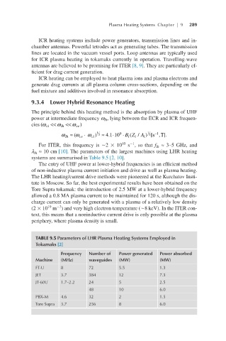
λ ≈ 10 cm [10]. The parameters of the largest machines using LHR heating
lh
systems are summarised in Table 9.5 [2, 10].
The entry of UHF power at lower-hybrid frequencies is an efficient method
of non-inductive plasma current initiation and drive as well as plasma heating.
The LHR heating/current drive methods were pioneered at the Kurchatov Insti-
tute in Moscow. So far, the best experimental results have been obtained on the
Tore Supra tokamak: the introduction of 2.5 MW at a lower-hybrid frequency
allowed a 0.8 MA plasma current to be maintained for 120 s, although the dis-
charge current can only be generated with a plasma of a relatively low density
19
−3
(2 × 10 m ) and very high electron temperature (∼8 keV). In the ITER con-
text, this means that a noninductive current drive is only possible at the plasma
periphery, where plasma density is small.
TABLE 9.5 Parameters of LHR Plasma Heating Systems Employed in
Tokamaks [2]
Frequency Number of Power generated Power absorbed
Machine (MHz) waveguides (MW) (MW)
FT-U 8 72 5.5 1.3
JET 3.7 384 12 7.3
JT-60U 1.7–2.2 24 5 2.5
48 10 6.0
PBX-M 4.6 32 2 1.5
Tore Supra 3.7 256 8 6.0