
Page 387 - Fundamentals of Magnetic Thermonuclear Reactor Design
P. 387
Mechanics of Magnetic Fusion Reactors Chapter | 12 365
components are used to calculate stress intensities and compare them with al-
lowable values. This express method is especially convenient for assessing
upper-strength limits of an MS completed with design.
12.4.3 Accident Scenarios
A short-circuit in windings and current feeding busbars is regarded as the worst-
case accident scenario for an MS [8]. Let us consider this hypothetical situation
in some detail using the ITER TFC as an example.
A short-circuit between the ends of a superconducting coil makes coil cur-
rent discharge impossible. This is exacerbated by the inductive effect of cur-
rent emergency discharge of other TFCs, making current in the affected coil
increase until the superconducting-to-resistive state transition occurs. The re-
sulting imbalance of ponderomotive forces disturbs the MS cyclic symmetry.
The ‘barrel vault’ may become unable to act as a support cylinder, and toroidal
forces arise causing mutual attraction between neighbouring coils.
A model of a 180-degree TFC segment with a symmetry plane crossing the
middle of the affected coil was adopted for ITER design. Symmetry conditions
are set to the segment boundaries. Special attention was paid to the wedging
operation. The interaction of TFC cases in an arc span was modelled using con-
tact elements. As the wedging efficiency increases with friction, the mechanical
condition on the TFC system was modelled with the assumption of minimum
friction, satisfying the friction coefficient µ = 0.1.
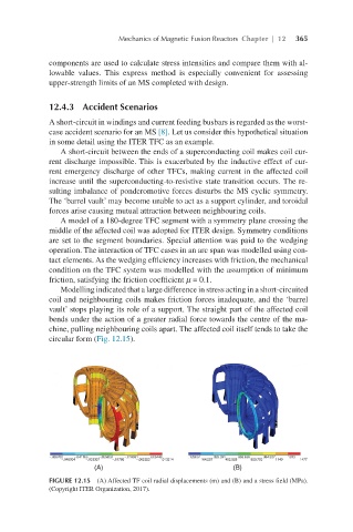
Modelling indicated that a large difference in stress acting in a short-circuited
coil and neighbouring coils makes friction forces inadequate, and the ‘barrel
vault’ stops playing its role of a support. The straight part of the affected coil
bends under the action of a greater radial force towards the centre of the ma-
chine, pulling neighbouring coils apart. The affected coil itself tends to take the
circular form (Fig. 12.15).
FIGURE 12.15 (A) Affected TF coil radial displacements (m) and (B) and a stress field (MPa).
(Copyright ITER Organization, 2017).