
Page 82 - Fundamentals of Ocean Renewable Energy Generating Electricity From The Sea
P. 82
74 Fundamentals of Ocean Renewable Energy
into account turbulence, and fluid structure interaction (e.g. [12]). It also
requires the collection of experimental data for model validation. However,
simplified analytical approaches such as actuator disk theory can provide a
good understanding of the flow field around horizontal axis turbines, as well
as some useful preliminary results at initial stages of design [13]. The analytical
methods are usually based on many assumptions, which should be considered
in application, as discussed here.
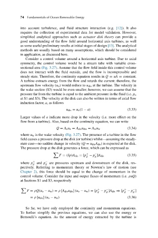
Consider a control volume around a horizontal axis turbine. Due to axial
symmetry, the control volume would be a stream tube with variable cross-
sectional area (Fig. 3.27). Assume that the flow field inside this control volume
does not interact with the fluid outside, and the flow is incompressible and
steady state. Therefore, the continuity equation results in Q = uA = constant.
A turbine extracts energy from the flow and retards the current; therefore, the
upstream flow velocity (u o ) would reduce to u dis at the turbine. The velocity in
the wake section (S3) would be even smaller; however, we can assume that the
pressure far from the turbine is equal to the ambient pressure in the fluid (i.e. p o
at S1 and S3). The velocity at the disk can also be written in terms of axial flow
induction factor, a, as follows
u dis = u o (1 − a) (3.33)
Larger values of a indicate more drop in the velocity (i.e. more effect on the
flow from a turbine). Also, based on the continuity equation, we can write
(3.34)
Q = A o u o = A dis u dis = A w u w
where u w is the wake velocity (Fig. 3.27). The presence of a turbine in the flow
field causes a pressure drop at the disk (or turbine) whilst—assuming the steady-
state case—no sudden change in velocity (Q = u dis A dis ) is expected at the disk.
The pressure drop at the disk generates a force, which can be expressed as
+ −
F = (δp)A dis =[p − p ]A dis (3.35)
d d
where p + and p − are pressures upstream and downstream of the disk, res-
d d
pectively. Referring to momentum theory or Newton’s law of motion (see
Chapter 2), this force should be equal to the change of momentum in the
control volume. Consider the input and output fluxes of momentum (i.e. ρuQ)
at Sections S1 and S3, respectively
+ − + −
F = ρQ(u o − u w ) = ρ [A dis u dis ] (u o − u w ) =[p − p ]A dis ⇒[p − p ]
d d d d
= ρ [u dis ] (u o − u w ) (3.36)
So far, we have only employed the continuity and momentum equations.
To further simplify the previous equations, we can also use the energy or
Bernoulli’s equation. As the amount of energy extracted by the turbine is