Page 204 - Fundamentals of Reservoir Engineering
P. 204

STABILIZED INFLOW EQUATIONS                                142

                     This PI improvement is probably pessimistic since it has been assumed that steady
                     state conditions prevail from the start of production. In fact, transient flow is more likely
                     during the initial stage which will give an early boost to production, in excess of that
                     calculated from steady state considerations. The manner in which the early transient
                     part of the production cycle can be accounted for will be described in Chapter 9, sec. 6.

                     EXERCISE 6.1 WELLBORE DAMAGE


               1)    A homogeneous formation has an average effective permeability k e. The effective
                     permeability out to a radius r a from the well has been altered (damage/stimulation) so
                     that its average value in this region is k a. Show that, for this situation, the skin factor
                     may be expressed as


                               k − k    r
                           S =  e   a  In  a                                                        (6.19)
                                 k      r
                                  a     w
                     where r w is the wellbore radius. Assume that for r< r a, the flow can be approximately
                     described under steady state conditions and that for r >r a, semi-steady state.

               2)    During drilling, a well is damaged out to a radius of 4 ft from the wellbore so that the
                     permeability within the damaged zone is reduced to 1/100 th of the undamaged
                     effective permeability. After completion the well is stimulated so that the permeability
                     out to a distance of 10 ft from the wellbore is increased to ten times the undamaged
                     permeability. What will be the PI ratio increase if the wellbore radius is 0.333 ft and the
                     drainage radius 660 ft?


                     EXERCISE 6.1 SOLUTION


                                                                                                p
                             Pressure                                                            e
                                                                        p a


                                                         k e   k a  p wf

                                                                  r w  r a                    r e
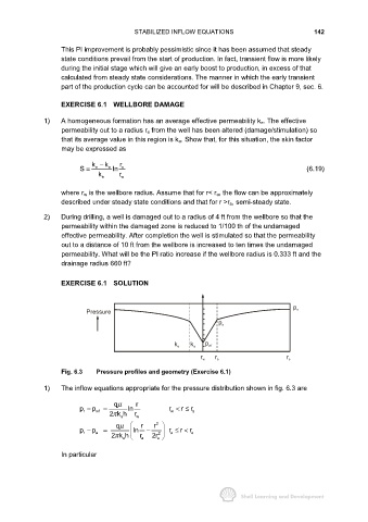
                     Fig. 6.3   Pressure profiles and geometry (Exercise 6.1)


               1)    The inflow equations appropriate for the pressure distribution shown in fig. 6.3 are

                                      qµ     r
                                                            r
                           p − p wf  =    ln            r < ≤  r a
                            r
                                                        w
                                    2k h    r w
                                     π
                                        a
                                      qµ       r   r
                                                    2
                                                           r
                           p − p a  =        ln  −  2    r ≤ <  r e
                            r
                                                        a
                                     2k h     r a  2r e
                                      π
                                         e
                     In particular
   199   200   201   202   203   204   205   206   207   208   209