
Page 210 - Fundamentals of Reservoir Engineering
P. 210
CHAPTER 7
THE CONSTANT TERMINAL RATE SOLUTION OF THE RADIAL DIFFUSIVITY
EQUATION AND ITS APPLICATION TO OILWELL TESTING
7.1 INTRODUCTION
The constant terminal rate solution, which describes the pressure drop in the wellbore
due to constant rate production, is the basic equation used in well test analysis. Apart
from during the brief transient flow period, (infinite reservoir case) the solution depends
critically on the reservoir boundary condition. In this chapter the constant terminal rate
solution is presented for a well situated within a no-flow boundary for all the
geometrical configurations considered by Matthews, Brons and Hazebroek and for any
value of the flowing time. The solutions are expressed in dimensionless form to simplify
and generalise the mathematics. Superposition of such solutions leads to a general
well test equation which can be applied to the analysis of any pressure test conducted
in the wellbore. In this chapter such tests are described for reservoirs containing a fluid
of small and constant compressibility (undersaturated oil). In Chapter 8 the same
techniques are applied to well test analysis in gas and gas saturated oil reservoirs.
7.2 THE CONSTANT TERMINAL RATE SOLUTION
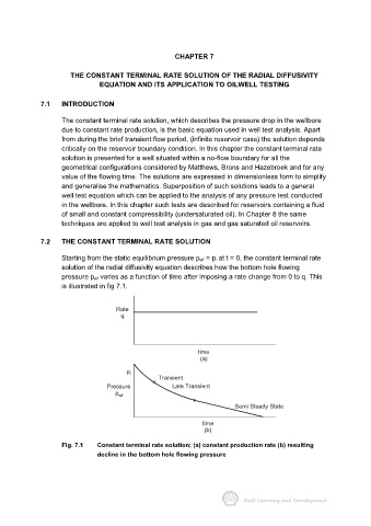
Starting from the static equilibrium pressure p wf = p i at t = 0, the constant terminal rate
solution of the radial diffusivity equation describes how the bottom hole flowing
pressure p wf varies as a function of time after imposing a rate change from 0 to q. This
is illustrated in fig 7.1.
Rate
q
time
(a)
p i
Transient
Pressure Late Transient
p wf
Semi Steady State
time
(b)
Fig. 7.1 Constant terminal rate solution; (a) constant production rate (b) resulting
decline in the bottom hole flowing pressure