
Page 224 - Fundamentals of The Finite Element Method for Heat and Fluid Flow
P. 224
CONVECTION HEAT TRANSFER
216
the solid wall are one-dimensional with two nodes if linear elements are used. The pressure
may be averaged over each one-dimensional element to calculate the average pressure over
the boundary element. If this average pressure is multiplied by the length of the element,
the normal pressure acting on the boundary element is obtained. If the pressure force is
multiplied by the direction cosine in the flow direction, we obtain the local pressure drag
force in the flow direction. Integration of these forces over the solid boundary gives the
drag force due to the pressure D p .
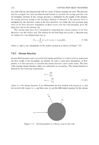
The viscous drag force D f is calculated by integrating the viscous traction in the flow
direction, over the surface area. The relation for the total drag force in the x 1 direction may
be written for a two-dimensional case as
= (7.186)
D x 1 [(−p + τ 11 )n 1 + τ 12 n 2 ]dA s
A s
where n 1 and n 2 are components of the surface normal n as shown in Figure 7.15.
7.8.3 Stream function
In most fluid dynamics and convection heat transfer problems, it is often easier to understand
the flow results if the streamlines are plotted. In order to plot these streamlines, or flow
pattern, it is first necessary to calculate the stream function values at the nodes. The lines
with constant stream function values, are referred to as streamlines. The stream function is
defined by the following relationships:
∂ψ
u 1 =
∂x 2
∂ψ
u 2 =− (7.187)
∂x 1
where ψ is the stream function. If we differentiate the first relation with respect to x 2 and
the second with respect to x 1 and then sum, we get the differential equation for the stream
n
A s
u a
Figure 7.15 Normal gradient of velocity close to the wall