
Page 227 - Fundamentals of The Finite Element Method for Heat and Fluid Flow
P. 227
CONVECTION HEAT TRANSFER
Walls: Both velocity components forced to zero (no-slip condition)
Initial conditions: Zero velocities and pressure at all points within the domain. 219
7.10.2 Solution
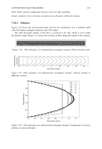
Figure 7.18 shows the unstructured mesh used for the calculations. It is a uniform mesh
with 3242 linear triangular elements and 1782 nodes.
The inlet Reynolds number of the flow is assumed to be 100, which is well within
the laminar range. Figure 7.19 shows the velocity profiles along the length of the channel.
Figure 7.18 Flow through a two-dimensional rectangular channel. Finite element mesh
Vertical distance 0.8 1
0.6
0.4
0.2
0
10
2
4
6
0
8
Horizontal velocity 12 14 16
Figure 7.19 Flow through a two-dimensional rectangular channel. Velocity profiles at
different sections
1
0.0
1.0
2.0
3.0
0.8
4.0
5.0
6.0
Vertical Distance 0.4
0.6
0.2
0
0 0.2 0.4 0.6 0.8 1 1.2 1.4
Horizontal velocity
Figure 7.20 Flow through a two-dimensional rectangular channel. Comparison of velocity
profiles at various distances