
Page 85 - Geochemical Remote Sensing of The Sub-Surface
P. 85
62 O.F. Putikov and B. Wen
T .... ...i ;2 I 13
~
9
1
............ i
I i
,t__ ..... .x. I /
4"" ~i ./" "'~, l~.]".." i /"
0 q)l (P2 q)3
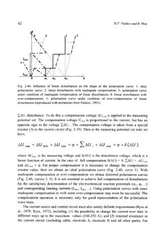
Fig. 2-40. Influence of linear disturbances on the shape of the polarisation curve: I- ideal
polarisation curve; 2- linear disturbances with inadequate compensation; 3- polarisation curve
under condition of inadequate compensation of linear disturbances; 4- linear disturbances with
over-compensation; 5- polarisation curve under condition of over-compensation of linear
disturbances (reproduced with permission from Putikov, 1993).
~AU~ disturbance. To do this a compensation voltage AUcom is applied to the measuring
potential set. The compensation voltage Ucom is proportional to the current, but has an
opposite sign to the voltage ZAU~. The compensation voltage is taken from a special
resistor (3) in the current circuit (Fig. 2-39). Then at the measuring potential set inlet we
have,
AU r,,~ - AU MN + AU :or. - ~n + ~ AU ; + AU :or. - ~ + a ( A U )
where AUmes is the measuring voltage and 6(AU) is the disturbance voltage, which is a
linear function of current. In the case of full compensation 5(AU) = 0, ZAU~ = -AUcom
and AUmes - q). For proper compensation it is necessary to change the compensation
resistor value, then we obtain an ideal polarisation curve (Fig. 2-40, curve 1). With
inadequate compensation or over-compensation we obtain distorted polarisation curves
(Fig. 2-40, curves 3, 5). It is not essential to achieve full compensation of disturbances
for the satisfactory determination of the electrochemical reaction potentials (q)l, q)2 ...)
and corresponding limiting currents (Iliml, Ilim2 ...). Using polarisation curves with some
inadequate compensation or with some over-compensation may even be successful. The
compensation operation is necessary only for good representation of the polarisation
wave steps.
The current source and current circuit must also satisfy definite requirements (Ryss et
al., 1978: Ryss, 1973), including: (1) the possibility to change the current over time in
different ways up to the maximum values (160-250 A); and (2) minimal resistance in
the current circuit (including cable, electrode A, electrode B and all other parts). For