
Page 147 - Geothermal Energy Systems Exploration, Development, and Utilization
P. 147
3.2 Drilling Equipment and Techniques 123
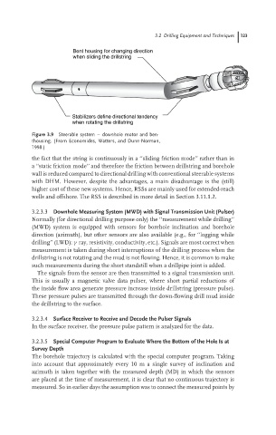
Bent housing for changing direction
when sliding the drillstring
Stabilizers define directional tendency
when rotating the drillstring
Figure 3.9 Steerable system – downhole motor and ben-
thousing. (From Economides, Watters, and Dunn-Norman,
1998.)
the fact that the string is continuously in a ‘‘sliding friction mode’’ rather than in
a ‘‘static friction mode’’ and therefore the friction between drillstring and borehole
wall is reduced compared to directional drilling with conventional steerable systems
with DHM. However, despite the advantages, a main disadvantage is the (still)
higher cost of these new systems. Hence, RSSs are mainly used for extended-reach
wells and offshore. The RSS is described in more detail in Section 3.11.1.2.
3.2.3.3 Downhole Measuring System (MWD) with Signal Transmission Unit (Pulser)
Normally (for directional drilling purpose only) the ‘‘measurement while drilling’’
(MWD) system is equipped with sensors for borehole inclination and borehole
direction (azimuth), but other sensors are also available (e.g., for ‘‘logging while
drilling’’ (LWD): γ ray, resistivity, conductivity, etc.). Signals are most correct when
measurement is taken during short interruptions of the drilling process when the
drillstring is not rotating and the mud is not flowing. Hence, it is common to make
such measurements during the short standstill when a drillpipe joint is added.
The signals from the sensor are then transmitted to a signal transmission unit.
This is usually a magnetic valve data pulser, where short partial reductions of
the inside flow area generate pressure increase inside drillstring (pressure pulse).
These pressure pulses are transmitted through the down-flowing drill mud inside
the drillstring to the surface.
3.2.3.4 Surface Receiver to Receive and Decode the Pulser Signals
In the surface receiver, the pressure pulse pattern is analyzed for the data.
3.2.3.5 Special Computer Program to Evaluate Where the Bottom of the Hole Is at
Survey Depth
The borehole trajectory is calculated with the special computer program. Taking
into account that approximately every 10 m a single survey of inclination and
azimuth is taken together with the measured depth (MD) in which the sensors
are placed at the time of measurement, it is clear that no continuous trajectory is
measured. So in earlier days the assumption was to connect the measured points by