
Page 164 - Geothermal Energy Systems Exploration, Development, and Utilization
P. 164
140 3 Drilling into Geothermal Reservoirs
Casing and 1/2 1/2
liner size, in. 4 4 5 5
Bit and hole 3/4 7/8 1/8 1/2 7/8
size, in. 4 5 6 6 7
Casing and 6 5/8 7 7 5/8 5/8 5/8
liner size, in. 7 3/4 8 9
Bit and hole 7/8 1/2 3/4 1/2 5/8 1/4
size, in. 7 8 8 9 10 12
Casing 5/8 9 5/8 3/4 11 5/8 13 3/8
size, in. 8 9 7/8 10 11 7/8 14
Bit and hole 5/8 1/4 3/4 1/2
size, in. 10 12 14 17
Casing 11 3/4 13 3/8
size, in. 11 7/8 14 16 20
Bit and hole
14 3/4 17 1/2 20 26
size, in.
Casing 30
size, in. 16 20 24
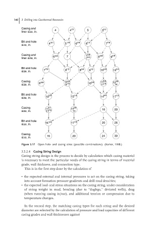
Figure 3.17 Open hole- and casing sizes (possible combinations). (Barker, 1998.)
3.5.2.4 Casing String Design
Casing string design is the process to decide by calculation which casing material
is necessary to meet the particular needs of the casing string in terms of material
grade, wall thickness, and connection type.
This is in the first step done by the calculation of
• the expected external and internal pressures to act on the casing string, taking
into account formation pressure gradients and drill mud densities;
• the expected load- and stress situations on the casing string, under consideration
of string weight in mud, bending (due to ‘‘doglegs,’’ deviated wells), drag
(when running casing in/out), and additional tension or compression due to
temperature changes.
In the second step, the matching casing types for each string and the desired
diameter are selected by the calculation of pressure and load capacities of different
casing grades and wall thicknesses against