
Page 175 - Geothermal Energy Systems Exploration, Development, and Utilization
P. 175
3.7 Well Completion Techniques 151
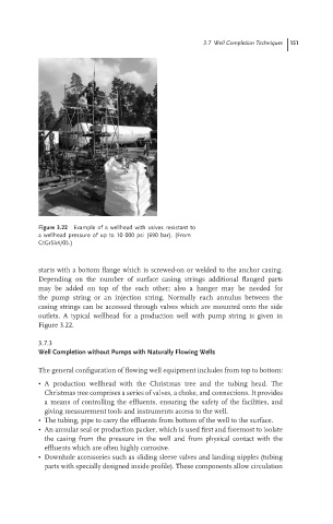
Figure 3.22 Example of a wellhead with valves resistant to
a wellhead pressure of up to 10 000 psi (690 bar). (From
GtGrSk4/05.)
starts with a bottom flange which is screwed-on or welded to the anchor casing.
Depending on the number of surface casing strings additional flanged parts
may be added on top of the each other; also a hanger may be needed for
the pump string or an injection string. Normally each annulus between the
casing strings can be accessed through valves which are mounted onto the side
outlets. A typical wellhead for a production well with pump string is given in
Figure 3.22.
3.7.3
Well Completion without Pumps with Naturally Flowing Wells
The general configuration of flowing well equipment includes from top to bottom:
• A production wellhead with the Christmas tree and the tubing head. The
Christmas tree comprises a series of valves, a choke, and connections. It provides
a means of controlling the effluents, ensuring the safety of the facilities, and
giving measurement tools and instruments access to the well.
• The tubing, pipe to carry the effluents from bottom of the well to the surface.
• An annular seal or production packer, which is used first and foremost to isolate
the casing from the pressure in the well and from physical contact with the
effluents which are often highly corrosive.
• Downhole accessories such as sliding sleeve valves and landing nipples (tubing
parts with specially designed inside profile). These components allow circulation