
Page 21 - HVAC Pump Handbook
P. 21
Rishel_CH02.qxd 20/4/06 5:13 PM Page 18
Physical Data for HVAC System Design
18 The Basic Tools
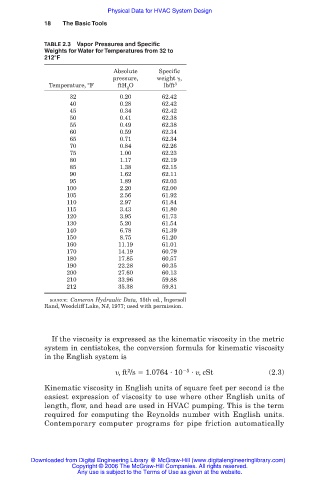
TABLE 2.3 Vapor Pressures and Specific
Weights for Water for Temperatures from 32 to
212°F
Absolute Specific
pressure, weight ,
Temperature, °F ftH O lb/ft 3
2
32 0.20 62.42
40 0.28 62.42
45 0.34 62.42
50 0.41 62.38
55 0.49 62.38
60 0.59 62.34
65 0.71 62.34
70 0.84 62.26
75 1.00 62.23
80 1.17 62.19
85 1.38 62.15
90 1.62 62.11
95 1.89 62.03
100 2.20 62.00
105 2.56 61.92
110 2.97 61.84
115 3.43 61.80
120 3.95 61.73
130 5.20 61.54
140 6.78 61.39
150 8.75 61.20
160 11.19 61.01
170 14.19 60.79
180 17.85 60.57
190 22.28 60.35
200 27.60 60.13
210 33.96 59.88
212 35.38 59.81
SOURCE: Cameron Hydraulic Data, 15th ed., Ingersoll
Rand, Woodcliff Lake, NJ, 1977; used with permission.
If the viscosity is expressed as the kinematic viscosity in the metric
system in centistokes, the conversion formula for kinematic viscosity
in the English system is
2
,ft /s 1.0764 10 5 , cSt (2.3)
Kinematic viscosity in English units of square feet per second is the
easiest expression of viscosity to use where other English units of
length, flow, and head are used in HVAC pumping. This is the term
required for computing the Reynolds number with English units.
Contemporary computer programs for pipe friction automatically
Downloaded from Digital Engineering Library @ McGraw-Hill (www.digitalengineeringlibrary.com)
Copyright © 2006 The McGraw-Hill Companies. All rights reserved.
Any use is subject to the Terms of Use as given at the website.