
Page 23 - HVAC Pump Handbook
P. 23
Rishel_CH02.qxd 20/4/06 5:13 PM Page 20
Physical Data for HVAC System Design
20 The Basic Tools
2.4.3 Vapor pressure and specific weight
for water, 212 to 450°F
Vapor pressures for water from 212 to 450°F, along with its specific
weight, are provided in Table 2.4; the values in the table, unlike
Table 2.3, are expressed in absolute pressures for determining the
minimum allowable pressures of hot water systems operating in this
temperature range. These pressures are used to calculate and avoid
cavitation at any point in these hot water systems.
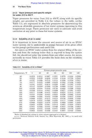
2.4.4 Solubility of air in water
It is important to know the amount and source of air in an HVAC
water system. Air is undesirable in pumps because of its great effect
on the pump’s performance and useful life.
Air enters an HVAC water system from the original filling of the sys-
tem and from the makeup water that is required to keep the system
full. Air should not enter the system from any other source. Air occurs
naturally in water. Table 2.5 provides the basic data on the solubility
of air in water.
TABLE 2.5 Solubility of Air in Water*
System gauge pressure, psig
Temperature, °F 0 20 40 60 80 100 120
40 0.0258 0.0613 0.0967 0.1321 0.1676 0.2030 0.2384
50 0.0223 0.0529 0.0836 0.1143 0.1449 0.1756 0.2063
60 0.0197 0.0469 0.0742 0.1014 0.1296 0.1559 0.1831
70 0.0177 0.0423 0.0669 0.0916 0.1162 0.1408 0.1654
80 0.0161 0.0387 0.0614 0.0840 0.1067 0.1293 0.1520
90 0.0147 0.0358 0.0569 0.0750 0.0990 0.1201 0.1412
100 0.0136 0.0334 0.0532 0.0730 0.0928 0.1126 0.1324
110 0.0126 0.0314 0.0501 0.0689 0.0877 0.1065 0.1252
120 0.0117 0.0296 0.0475 0.0654 0.0833 0.1012 0.1191
130 0.0107 0.0280 0.0452 0.0624 0.0796 0.0968 0.1140
140 0.0098 0.0265 0.0432 0.0598 0.0765 0.0931 0.1098
150 0.0089 0.0251 0.0413 0.0574 0.0736 0.0898 0.1060
160 0.0079 0.0237 0.0395 0.0553 0.0711 0.0869 0.1027
170 0.0068 0.0223 0.0378 0.0534 0.0689 0.0844 0.1000
180 0.0055 0.0208 0.0361 0.0514 0.0667 0.0820 0.0973
190 0.0041 0.0192 0.0344 0.0496 0.0647 0.0799 0.0950
200 0.0024 0.0175 0.0326 0.0477 0.0628 0.0779 0.0930
210 0.0004 0.0155 0.0306 0.0457 0.0607 0.0758 0.0909
*Ratio of absorbed air volume to water volume expressed as a decimal.
SOURCE: Technical Bulletin 8–80, Amtrol, Inc., West Warrwick, RI, 1985, p. 14; used with
permission.
Downloaded from Digital Engineering Library @ McGraw-Hill (www.digitalengineeringlibrary.com)
Copyright © 2006 The McGraw-Hill Companies. All rights reserved.
Any use is subject to the Terms of Use as given at the website.