
Page 353 - HVAC Pump Handbook
P. 353
Rishel_CH12.qxd 20/4/06 6:39 PM Page 350
Pumps for Process Cooling
350 Pumps for Open HVAC Cooling Systems
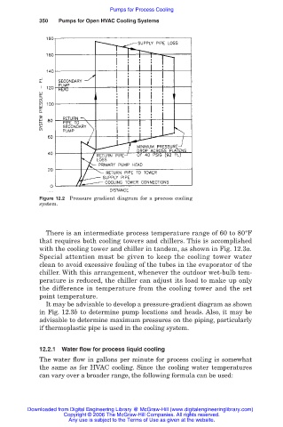
Figure 12.2 Pressure gradient diagram for a process cooling
system.
There is an intermediate process temperature range of 60 to 80°F
that requires both cooling towers and chillers. This is accomplished
with the cooling tower and chiller in tandem, as shown in Fig. 12.3a.
Special attention must be given to keep the cooling tower water
clean to avoid excessive fouling of the tubes in the evaporator of the
chiller. With this arrangement, whenever the outdoor wet-bulb tem-
perature is reduced, the chiller can adjust its load to make up only
the difference in temperature from the cooling tower and the set
point temperature.
It may be advisable to develop a pressure-gradient diagram as shown
in Fig. 12.3b to determine pump locations and heads. Also, it may be
advisable to determine maximum pressures on the piping, particularly
if thermoplastic pipe is used in the cooling system.
12.2.1 Water flow for process liquid cooling
The water flow in gallons per minute for process cooling is somewhat
the same as for HVAC cooling. Since the cooling water temperatures
can vary over a broader range, the following formula can be used:
Downloaded from Digital Engineering Library @ McGraw-Hill (www.digitalengineeringlibrary.com)
Copyright © 2006 The McGraw-Hill Companies. All rights reserved.
Any use is subject to the Terms of Use as given at the website.