
Page 78 - HVAC Pump Handbook
P. 78
Rishel_CH03.qxd 20/4/06 5:35 PM Page 75
Piping System Friction
Piping System Friction 75
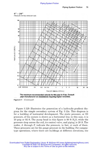
Figure 3.11 (Continued)
Figure 3.12b illustrates the generation of a hydraulic-gradient dia-
gram for the simple secondary system of Fig. 3.12a. This diagram is
for a building of horizontal development. The static pressure, or fill
pressure, of the system is shown as a horizontal line; in this case, it is
40 psig or 92 ft. The pump head in this figure is 90 ft H O, while the
2
pressure drop across the coil, its control valve, and piping, is 20 ft. The
nodes, A through F, indicate the pressure, in feet, at each of them.
These pressures are for the gauge pressure in the building. For campus-
type operations, where there are buildings at different elevations, the
Downloaded from Digital Engineering Library @ McGraw-Hill (www.digitalengineeringlibrary.com)
Copyright © 2006 The McGraw-Hill Companies. All rights reserved.
Any use is subject to the Terms of Use as given at the website.