
Page 109 - Hacking Roomba
P. 109
90 Part I — Interfacing
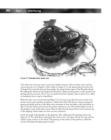
FIGURE 5-1: Roomba drive motor unit
The other four wires are used to sense the wheel’s rotation. I discuss those wires and the
sensors they go to in Chapter 6. Also visible in Figure 5-1 is the spring and pivot point (the
X-shaped bit toward the bottom) that enables the spring-loaded aspect of the Roomba wheels.
By making the wheels spring-loaded, the Roomba is always pressing down on the ground and
getting positive traction, even if it’s not entirely level (for example, when it drives over cables
or transitions from a rug to a hard floor).
With the main cover unscrewed (see Figure 5-2), it’s easy to see that the unit consists of an
electric motor and a gearbox, joined by a rubber drive belt. The belt was chosen instead of
gearing probably because a belt offers more resistance to dirt and offers a fail-safe ability to
slip in case the wheel can’t turn but the motor continues to run. The slotted wheel on top of
the gearbox is part of the drive sensor. That it’s after the belt means that it won’t measure any
of the slipping, which makes for more accurate odometry.
Inside the triple-sealed gearbox is the planetary (also called epicyclic) gearing system (see
Figure 5-3). The shaft driven directly by the motor is the “sun” gear and the two sets of three
“planet” gears connect to the wheel. The gearing on the inside of the gearbox is called the
annulus and keeps the planet gears in place.