
Page 261 - Hacking Roomba
P. 261
242 Part III — More Complex Interfacing
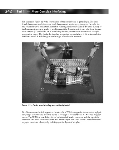
You can see in Figure 12-9 the construction of the carrier board is quite simple. The dual
female headers are made from two single headers used previously, cut down to the right size
and soldered next to each other. Instead of soldering the Roomba Mini-DIN cable directly to
the board, another single header is used to accept the Roomba prototyping plug from the pre-
vious chapter. (If you build a lot of interfacing circuits, you may want to construct a couple
prototyping plugs.) The header for the plug is mounted horizontally so it fits underneath the
WiMicro board. A little hot glue on the edges of the header secures it.
FIGURE 12-9: Carrier board wired up and continuity tested
To offer some mechanical support to the side of the WiMicro opposite its connector, a physi-
cally larger capacitor was used and placed at the edge of the board near the Roomba plug con-
nector. The WiMicro board then sits on both the dual header connector and the top of the
capacitor. This takes the strain off the dual header. If you aren’t able to use a capacitor in this
way, you can create a bumper by building up a few layers of hot glue.