
Page 285 - Hacking Roomba
P. 285
266 Part III — More Complex Interfacing
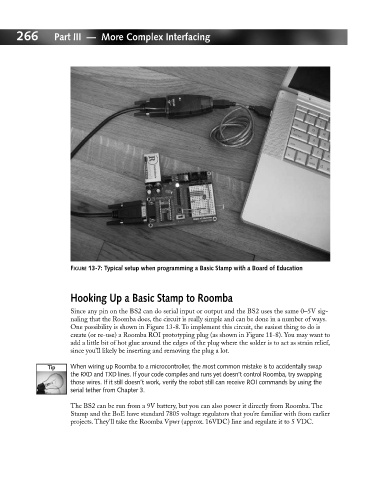
FIGURE 13-7: Typical setup when programming a Basic Stamp with a Board of Education
Hooking Up a Basic Stamp to Roomba
Since any pin on the BS2 can do serial input or output and the BS2 uses the same 0–5V sig-
naling that the Roomba does, the circuit is really simple and can be done in a number of ways.
One possibility is shown in Figure 13-8. To implement this circuit, the easiest thing to do is
create (or re-use) a Roomba ROI prototyping plug (as shown in Figure 11-8). You may want to
add a little bit of hot glue around the edges of the plug where the solder is to act as strain relief,
since you’ll likely be inserting and removing the plug a lot.
When wiring up Roomba to a microcontroller, the most common mistake is to accidentally swap
the RXD and TXD lines. If your code compiles and runs yet doesn’t control Roomba, try swapping
those wires. If it still doesn’t work, verify the robot still can receive ROI commands by using the
serial tether from Chapter 3.
The BS2 can be run from a 9V battery, but you can also power it directly from Roomba. The
Stamp and the BoE have standard 7805 voltage regulators that you’re familiar with from earlier
projects. They’ll take the Roomba Vpwr (approx. 16VDC) line and regulate it to 5 VDC.