
Page 286 - Hacking Roomba
P. 286
Chapter 13 — Giving Roomba a New Brain and Senses 267
Vin
1 24
SOUT VIN
2 23
SIN VSS
3 22
ATN RES
4 21
GND VDD
5 20 Vss
P0 P15
6 19
P1 P14
7 18
P2 P13
8 17
P3 P12
9 16
P4 P11
10 15
P5 P10
11 14
R1 12 P6 P9 13
P7 P8 mini-din 8pin
220 Vss 8 7
LED1 DD 6 5
TXD
4
RXD 3
Vss 2
+16VDC 1
X1
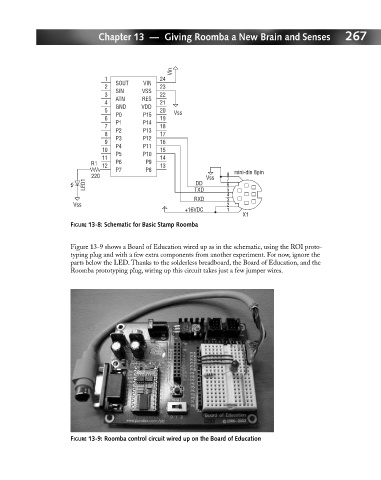
FIGURE 13-8: Schematic for Basic Stamp Roomba
Figure 13-9 shows a Board of Education wired up as in the schematic, using the ROI proto-
typing plug and with a few extra components from another experiment. For now, ignore the
parts below the LED. Thanks to the solderless breadboard, the Board of Education, and the
Roomba prototyping plug, wiring up this circuit takes just a few jumper wires.
FIGURE 13-9: Roomba control circuit wired up on the Board of Education