
Page 310 - Hacking Roomba
P. 310
Chapter 13 — Giving Roomba a New Brain and Senses 291
ARDUINO_8-13
8
7
6
ARDUINO_POWER 5
PWM2 4
4
3 PWM1 3
2 GND PWM0 2
1 9V 1
BLUE GREEN RED Digital
1k R3 1k R2 220 R1 ARDUINO_0-7
8
7
mini-din 8pin 8 GND 6
7 GND 5
6 DD 4
5 TXD
4 3
3 RXD TX 2
2 RX 1
1 +16VDC
X1
Digital
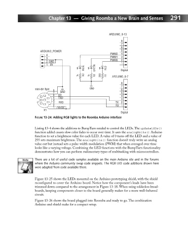
FIGURE 13-24: Adding RGB lights to the Roomba Arduino interface
Listing 13-4 shows the additions to BumpTurn needed to control the LEDs.The updateLEDs()
function added causes slow color fades to occur over time. It uses the analogWrite() Arduino
function to set a brightness value for each LED. A value of 0 turns off the LED and a value of
255 sets maximum brightness. The analogWrite() function doesn’t truly write an analog
value out but instead sets a pulse-width modulation (PWM) that when averaged over time
looks like a varying voltage. Combining the LED functions with the BumpTurn functionality
demonstrates how you can perform rudimentary types of multitasking with microcontrollers.
There are a lot of useful code samples available on the main Arduino site and in the forums
where the Arduino community swap code snippets. The RGB LED code additions shown here
were adapted from code available there.
Figure 13-25 shows the LEDs mounted on the Arduino prototyping shield, with the shield
reconfigured to cover the Arduino board. Notice how the component’s leads have been
trimmed down compared to the arrangement in Figure 13-18. When using solderless bread-
boards, keeping components closer to the board generally makes for a more well-behaved
circuit.
Figure 13-26 shows the board plugged into Roomba and ready to go. The combination
Arduino and shield make for a compact setup.