
Page 374 - Hacking Roomba
P. 374
Chapter 15 — RoombaCam: Adding Eyes to Roomba 355
Building a USB Serial Tether from a Phone Sync Cable Continued
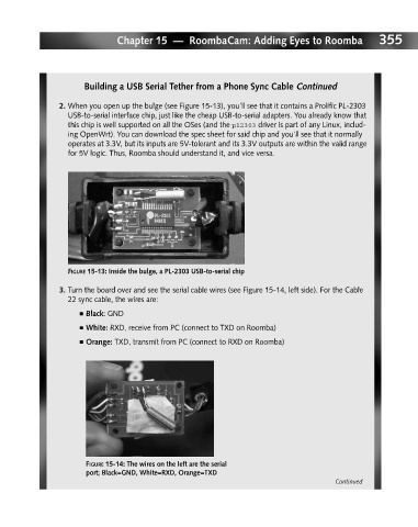
2. When you open up the bulge (see Figure 15-13), you’ll see that it contains a Prolific PL-2303
USB-to-serial interface chip, just like the cheap USB-to-serial adapters. You already know that
this chip is well supported on all the OSes (and the pl2303 driver is part of any Linux, includ-
ing OpenWrt). You can download the spec sheet for said chip and you’ll see that it normally
operates at 3.3V, but its inputs are 5V-tolerant and its 3.3V outputs are within the valid range
for 5V logic. Thus, Roomba should understand it, and vice versa.
FIGURE 15-13: Inside the bulge, a PL-2303 USB-to-serial chip
3. Turn the board over and see the serial cable wires (see Figure 15-14, left side). For the Cable
22 sync cable, the wires are:
■ Black: GND
■ White: RXD, receive from PC (connect to TXD on Roomba)
■ Orange: TXD, transmit from PC (connect to RXD on Roomba)
FIGURE 15-14: The wires on the left are the serial
port; Black=GND, White=RXD, Orange=TXD
Continued