
Page 375 - Hacking Roomba
P. 375
356 Part III — More Complex Interfacing
Building a USB Serial Tether from a Phone Sync Cable Continued
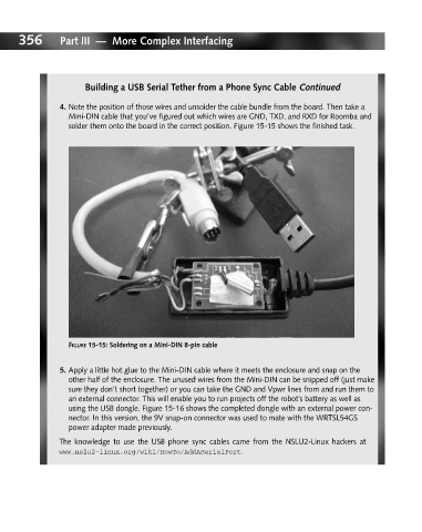
4. Note the position of those wires and unsolder the cable bundle from the board. Then take a
Mini-DIN cable that you’ve figured out which wires are GND, TXD, and RXD for Roomba and
solder them onto the board in the correct position. Figure 15-15 shows the finished task.
FIGURE 15-15: Soldering on a Mini-DIN 8-pin cable
5. Apply a little hot glue to the Mini-DIN cable where it meets the enclosure and snap on the
other half of the enclosure. The unused wires from the Mini-DIN can be snipped off (just make
sure they don’t short together) or you can take the GND and Vpwr lines from and run them to
an external connector. This will enable you to run projects off the robot’s battery as well as
using the USB dongle. Figure 15-16 shows the completed dongle with an external power con-
nector. In this version, the 9V snap-on connector was used to mate with the WRTSL54GS
power adapter made previously.
The knowledge to use the USB phone sync cables came from the NSLU2-Linux hackers at
www.nslu2-linux.org/wiki/HowTo/AddASerialPort.