
Page 174 - Handbook Of Multiphase Flow Assurance
P. 174
170 5. Flow restrictions and blockages in operations
TABLE 5.8 Procedure to calculate wax diffusion coefficient from a deposition experiment data such as a
laboratory cold finger—cont’d
Flux = D (C_WAT − C wall )/L_diff - Assume Fick's law
Oil heat capacity, J/kg K 1917 per PVT tool at 1 bar, 36 °C
Oil thermal conductivity, W/m K 0.152 per PVT tool at 1 bar, 36 °C
Reynolds 22 = dens.oil × flow velocity × OD_finger/viscosity
Prandtl 517 = viscosity × heat capacity/thermal conductivity
Thermal sublayer, cm 0.001386 delta_thermal/L = 0.664 Pr^(−2/3)/sqrt(Re)
Flow sublayer, cm 0.1263 delta_flow = 0.37 diam_finger^(4/5) *(kinem visc/veloc)^0.2
WAT, °C 36
Distance fraction 0.8 = 1-(Thot − WAT)/(Thot − Twall)
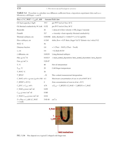
L, cm 0.6 = R_flask-R-OD
L diffusion, cm 0.00139 Using thermal sublayer
2
Flux, g/in. /h 0.01215 = mass_initial_deposition/time_initial_deposition/area_deposit
2
Flux, g/cm /s 5.2E-07
T, °C 40 Hot oil temperature
T wall , °C 20 Cold finger temperature
T_WAT, °C 36
T_BP237 −32 Wax content measurement temperature
C_WAT, wt% = g wax/g oil × 100 6.2 Maximum concentration of wax in oil at WAT 36 °C
C_BP237 (−32 °C) 0 Zero concentration of wax in oil at −32 °C
C_20°C = C wall , wt% 4.74 =(T wall − T_BP237)/(T_WAT − T_BP237) × C_WAT
3
C_WAT, g wax/cm oil 0.053
3
C wall , g wax/cm oil 0.040
3
C_WAT-C wall , g wax/cm oil 0.012
2
D = Flux × L_diff/(C_WAT 5.9E-08 cm /s
− Cwall)
FIG. 5.36 Wax deposit on a typical U-shaped cold finger test.